
Attention! If during the repair of the gearbox, at least one of the following parts was replaced: clutch housings or gearboxes, differential housing or differential bearings, then it is necessary to select an adjusting ring for differential bearings (see «Selection of an adjusting ring for differential bearings»).
To disassemble and assemble the gearbox and troubleshoot its parts on a car, you will need: socket wrenches (heads) «on 10», «at 13», «at 32», keys «on 10» And «at 17», large screwdriver, punch, hammer, circlip pliers, impact screwdriver.
1. Remove the gearbox from the car (see «Removal and installation of a transmission»). Clean it of dirt and wash the outside.
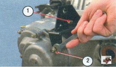
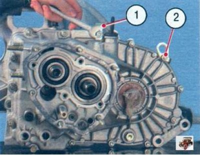
2. Remove bolt 1 (a flat washer is installed under its head), unscrew nut 2 (there is a spring washer underneath) securing the clutch cable bracket and remove the bracket.
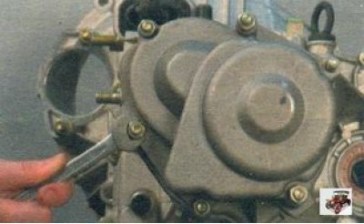
3. Turn away other five nuts of fastening of a back cover of a transmission.
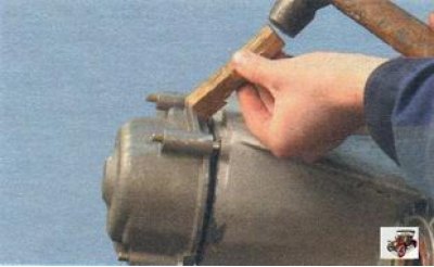
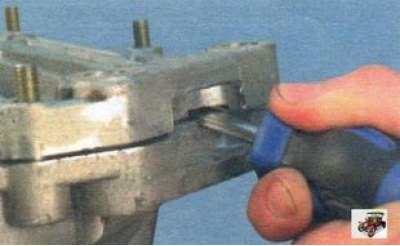
4. Leaning a wooden spacer or a soft metal drift on the tide of the gearbox cover, gently slide it along the studs with gentle hammer blows...
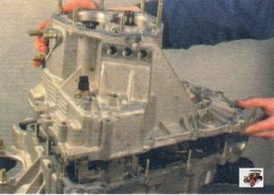
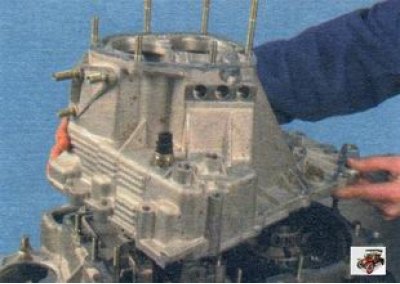
5.... and remove the rear cover from the gearbox.
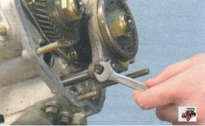
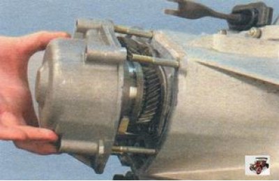
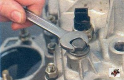
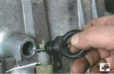
6. Turn out a bolt of fastening of a fork of V transfer (there is a spring washer under the head of the bolt).
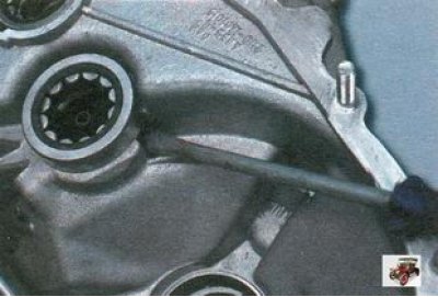
7. Secure the gearbox shafts from turning. To do this, turn on the V gear by moving the synchronizer clutch along with the fork so that the splines of the clutch engage with the gear...
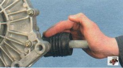
8.... then turn on the III or IV gear by moving the gear shift rod.
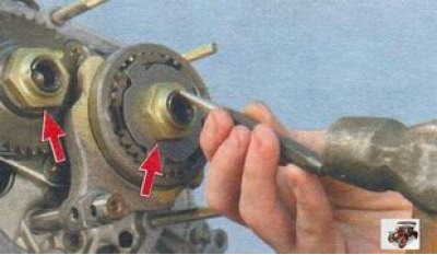
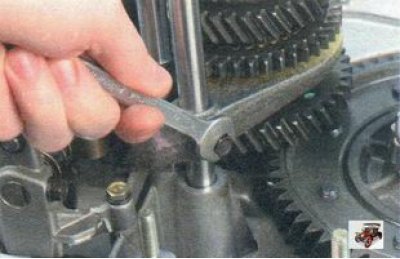
9. Loosen the nuts securing the primary and secondary shafts.
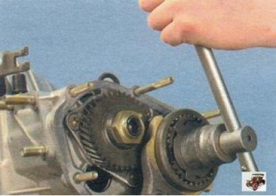
10. Turn away nuts of fastening of primary and secondary shaft. To do this, you need to make a lot of effort, since the nuts are tightened with a large moment.
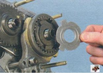
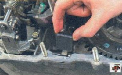
11. Remove the thrust plate from the synchronizer.
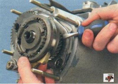
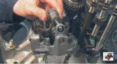
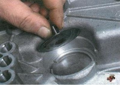
12. Sliding the driven gear of the 5th gear with a screwdriver (thereby compressing the synchronizer hub from the shaft), remove the gear together with the synchronizer and fork from the secondary shaft.
Attention! Make sure that the synchronizer sleeve does not come off the hub: the spring-loaded synchronizer locking balls may crumble.
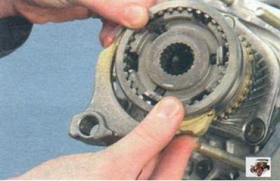
13. Remove the plug from the groove of the synchronizer sleeve.
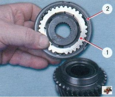
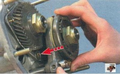
14. Remove the V gear from the synchronizer. Mark blocking ring 1 with respect to coupling 2 and remove it. During operation, the teeth of the ring are run in to the teeth of the coupling, therefore, during assembly, the ring must be installed in the same position. If the synchronizer is not supposed to be disassembled, tie it with wire or rope so that it does not crumble.
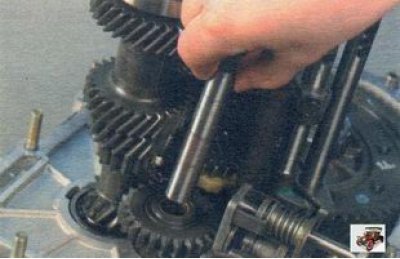
15. Remove the sleeve from the secondary shaft of the gearbox.
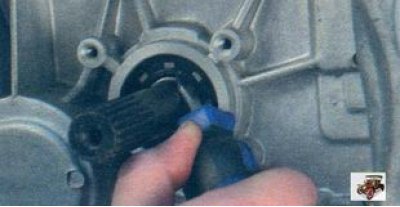
16. Remove the 5th gear drive gear from the input shaft. Remember how it was installed.
17. Using a screwdriver, remove the thrust washer from the output shaft.
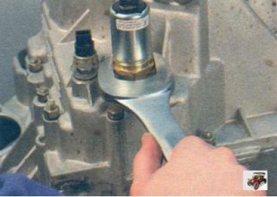
18. Loosen the reverse gear lock solenoid...
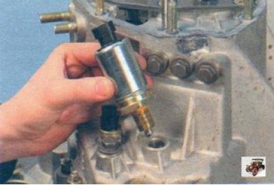
19.... and unscrew the solenoid from the gearbox housing.
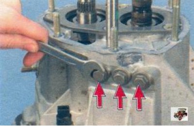
20. Turn out three plugs of clamps...
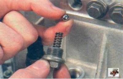
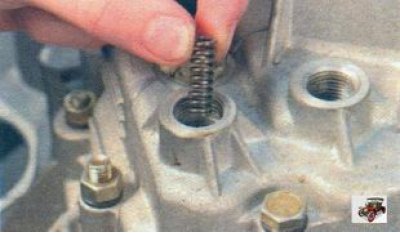
21.... and carefully remove the retainer balls with springs.
22. Having unscrewed the plug of the reverse gear, remove the sealing ring, if it remains on the gearbox housing...
23....and then remove the detent spring.
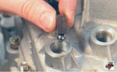
24. Remove the detent ball. This can be done conveniently by using a small, strong magnet or by tilting the gearbox on its side.
25. Remove the clutch release bearing (see «Replacing the clutch release bearing»).
26. Remove the guide sleeve of the clutch release bearing by unscrewing the three bolts of its fastening (see «Replacing gearbox seals»).
Helpful advice. When disassembling the gearbox, it is recommended to replace the input shaft oil seal, regardless of its condition, since in the event of an oil leak through the oil seal in operation, its replacement in a car is very laborious.
27. Remove the clutch release fork (see «Replacing the clutch release fork»).
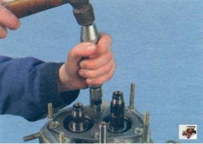
28. Using an impact screwdriver, remove the four screws (spring washers are installed under them) mounting plate bearings...
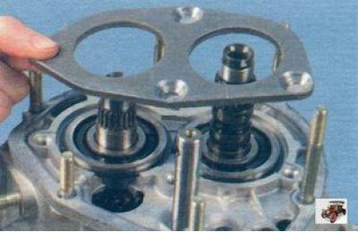
29.... and remove the gearbox bearing plate.
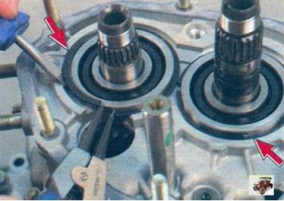
30. Opening with pliers and prying with a screwdriver, remove the retaining rings of the gearbox bearings.
31. Turn away twelve nuts and a bolt of fastening of cases of a transmission. Pay attention and remember under which nuts the holder 1 and eye 2 are installed. Spring washers are installed under the nuts and bolt.

32. Resting a wooden spacer or a soft metal drift against the edges of the three special grooves located along the perimeter of the crankcases, separate the gearbox housing from the clutch housing with light hammer blows.
Note. In addition to the method described above, it is possible to separate the gearbox housing from the clutch housing with a screwdriver by inserting it into the slots of special grooves along the perimeter of the crankcases.
33. Slightly lift the gearbox housing...
34.... turn the crankcase counterclockwise so that the tide inside the crankcase comes out from under the input shaft gear, and remove the gearbox housing from the clutch housing.
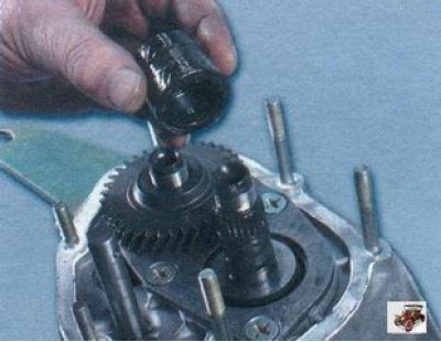
35. Remove the magnet from the clutch housing.
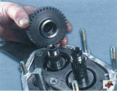
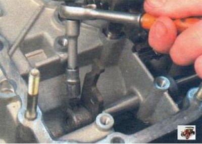
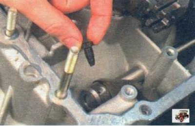
36. Before removing the gear selection mechanism, remove the reverse intermediate gear by removing the intermediate gear shaft...
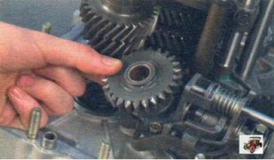
37.... slide the intermediate gear all the way into the gear selection mechanism, turn it 30-40°and, removing it from under the shaft gears, remove it.
38. Turn out three bolts of fastening of the mechanism of a choice of transfers (spring washers are installed under the bolt heads)...
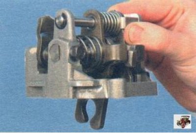
39.... and remove the gear selection mechanism.
Note. Removal of the gear selector mechanism for its replacement is shown. If replacement is not necessary, the gear selector only needs to be removed if the shift rod needs to be removed (see below). The mechanism does not interfere with the removal of the primary and secondary shafts of the gearbox, as well as the differential, and can be left in its place.
Note. In operation, the gear selection mechanism almost never goes out of order, since its parts working in gear oil wear out slowly and evenly. Increased backlashes in the interfaces of the mechanism also do not lead to its complete failure. Therefore, the disassembly of the gear selection mechanism is not shown on the site. In case of need for replacement, the mechanism is supplied as a spare parts assembly.
Attention! Please note that the gear selection mechanism, while externally similar to the mechanism of cars «tenth» VAZ family differs from it in design.
40. Loosen the locking bolt securing the gear lever to the rod...
41.... remove the bolt...
42.... and, having moved the rod, remove the gear lever.
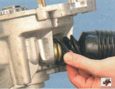
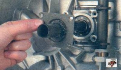
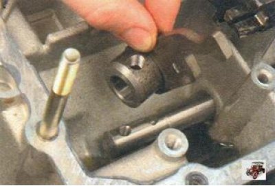
43. Remove the cover of the hinge of the gearshift rod from the flanging of the holder of the stuffing box of the rod...
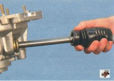
44.... and remove the gearshift rod from the clutch housing.
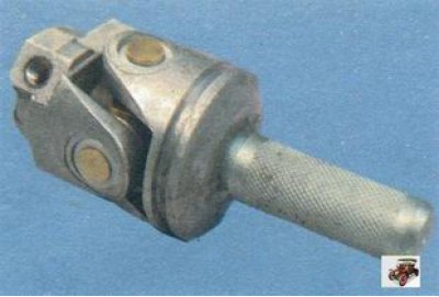
Note. The design of the hinge of the gearshift rod is non-separable. If play appears in the joints of the hinge, it must be replaced as an assembly. To do this, disconnect the hinge from the gearshift rod by unscrewing the locking bolt of its fastening (see «Replacing gearbox seals»).
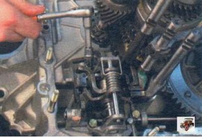
45. For further disassembly of the gearbox (Operation shown with gear selector and reverse idler installed) unscrew the bolt securing the fork of I-II gears to the stem.
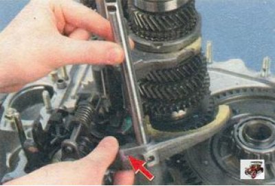
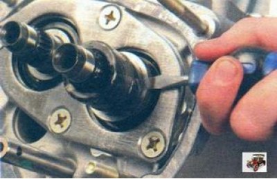
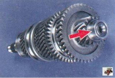
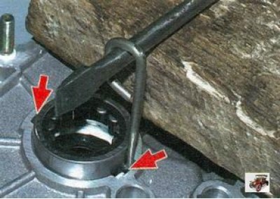
46. Slightly lift the 1st-2nd shift shaft until it is clear of its support in the clutch housing, and turn counterclockwise until the shift fork head (shown by arrow) disengaged from the locking bracket of the gear selection mechanism. Remove the stem fork from the groove of the synchronizer sleeve and remove the stem with the fork.
Note. Unless necessary, it is not recommended to remove the shift forks from the rods so as not to confuse them during assembly.
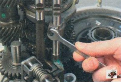
47. Turn out a bolt of fastening of a plug of switching of III-IV transfers.
48. Turning the III-IV gear shift rod, disengage the head of its fork from engagement with the gear lever. Then slightly lift the rod so that it comes out of the support in the clutch housing, and, having removed the rod fork from the groove of the synchronizer clutch, remove the rod with the gear shift fork.
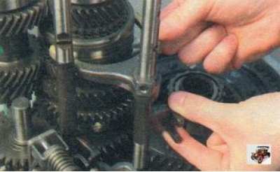
49. Turning the 5th gear engagement rod, disengage its head from the locking bracket. Remove the stem by removing it from the support.
50. Remove the reverse idle gear (see paragraphs. 36.37).
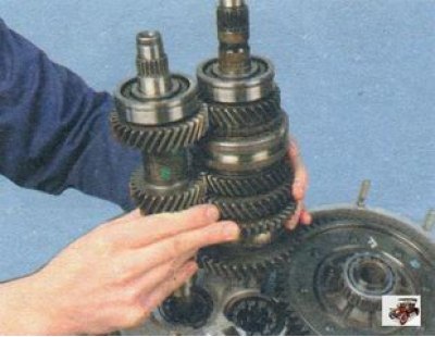
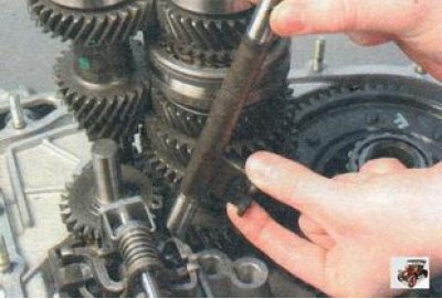
51. Slightly shaking, take out at the same time the primary and secondary shafts of the gearbox.
Note. When both shafts of the gearbox are removed, the inner races of the front bearings remain on the shafts.
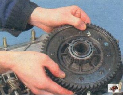
52. Remove the differential from the clutch housing.
53. Take out the pointer (probe) oil level in the gearbox.
54. If necessary, remove the speed sensor (see «Vehicle speed sensor») and unscrew the reverse light switch from the gearbox housing (see «Reversing light switch replacement»).
55. A special puller is used to press out the front bearing of the secondary shaft. If not, press out the output shaft bearing with a screwdriver.
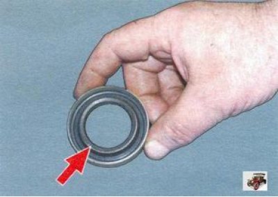
56. Remove the oil collector installed under the output shaft bearing.
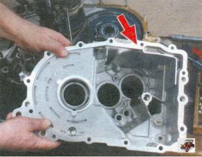
57. There is also a special puller for pressing out the input shaft front bearing. If it is not available, bend the device in the form of a hard wire hook. Insert the tool into one of the two grooves in the gearbox housing and hook the hook under the bearing. Then with a screwdriver (placing a wooden block) press the bearing out of the gearbox housing by applying force to the opposite end of the screwdriver with hammer blows and alternately rearranging the hook in the grooves.
58. Press the new front bearings of the gearbox shafts into the clutch housing as far as they will go using a suitable mandrel.
59. To replace the clutch housing, remove the bearing from it (see «Replacing the clutch release bearing») and clutch release fork (see «Replacing the clutch release fork»), press out seals (see «Replacing gearbox seals»).
60. Inspect the clutch and gearbox housings, as well as the rear cover. They should not have cracks or chips. There should be no nicks, scratches, dents, etc. on the mating surfaces. Remove minor damage with sandpaper. If severely damaged, replace defective parts.
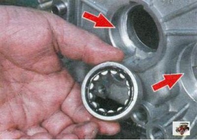
61. Check the bearing seats in the clutch and gearbox housings. These surfaces must not show signs of wear or damage. Otherwise, replace the clutch and gearbox housings.
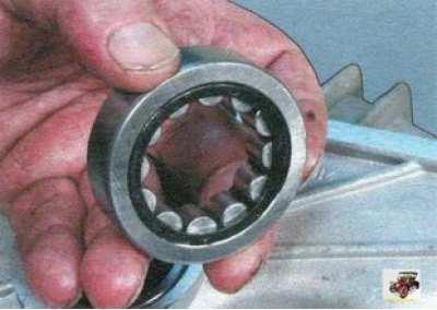
62. If the raceways, cage or rollers are damaged and if play is found in the bearing, checking the bearing by installing it on the shaft (radial clearance in the bearing must not exceed 0.07 mm), replace it.
63. Check up a condition of rods of a gear change. Replace bent rods with scuffs, burrs or worn holes for retainers. Replace the forks if they are bent or their tabs are worn out.
64. Check the axle shaft seals. The axle shaft seals must not be warped or torn. The working edge of the semi-axle oil seal must be even, without tears, dents and rubber sagging. The gland spring must not be broken or stretched. Replace defective axle shaft seals.
65. Check and, if necessary, replace the seals of the input shaft and the gear shift rod.
66. Clean the magnet of wear particles. If the magnet is cracked or magnetically weak, replace the magnet.
67. Thoroughly clean the mating surfaces of the clutch and gearbox housings, as well as the rear cover, from the old sealant.
Assemble the gearbox in reverse order of disassembly, subject to the following.
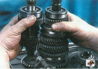
1. Before installing the primary and secondary shafts, engage the teeth of their gears and, in this position, install them in the clutch housing.
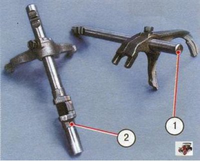
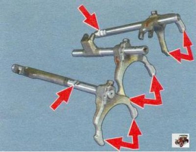
2. Pay attention to how the forks are installed on the gearshift rods:
- 1 - rod with shift fork I - II gears;
- 2 - a rod with a fork for switching III - IV gears.
3. Please note that the selector rod pivot bolt is different from the other similar bolts used in the gearbox to attach the forks and gear lever. It is longer and cadmium (golden color coating). Do not replace this bolt with others. Before screwing this and other similar bolts, degrease the threaded part of the bolt and apply TB-1324 glue to it, and in its absence, an anaerobic thread lock.
4. Copiously lubricate all friction parts with gear oil.
5. Don't forget to replace the magnet.
6. Before installing the gearbox housing on the clutch housing and the rear cover on the gearbox housing, apply to their mating surfaces (around the perimeter) sealant TB-1215 or KLT-75TM with a continuous roller with a diameter of 2 mm.