
To repair the output shaft of the gearbox on a car, you will need: two large screwdrivers with flat blades, a hammer, a soft metal drift, a set of flat probes.
1. Remove the secondary shaft from the gearbox (see «Disassembly and assembly of the gearbox and troubleshooting of its parts»).
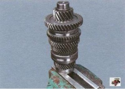
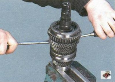
2. Clamp with a little effort the secondary shaft of the gearbox in a vise, with pads on the jaws of soft metal.
Note. The output shaft of the gearbox must be clamped in a vise with soft pads on the jaws for the inner ring of the front bearing. Tighten the vise so that the output shaft can be tilted by hand to avoid damaging the bearing race surface.
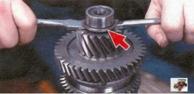
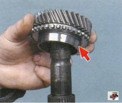
3. Remove from the forward end of a secondary shaft a lock ring established under an internal ring of the forward bearing.
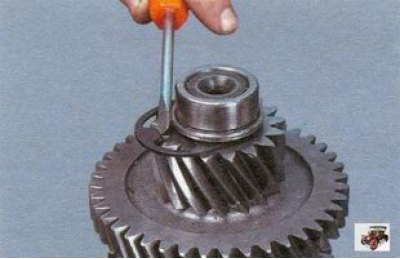
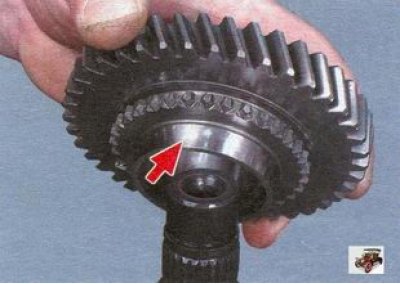
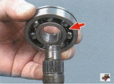
4. Using two screwdrivers, press the front bearing inner race off the output shaft. The collar of the ring is directed towards the final drive gear.
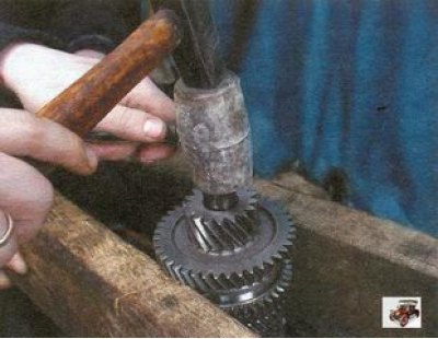
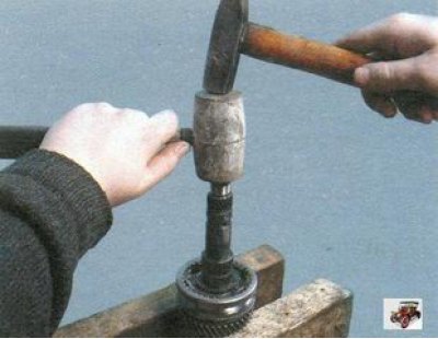
5. Having opened the vice, support the gear wheel of the 1st gear on two supports. With hammer blows through a wooden gasket, press the 1st gear gear with the final drive gear from the shaft.
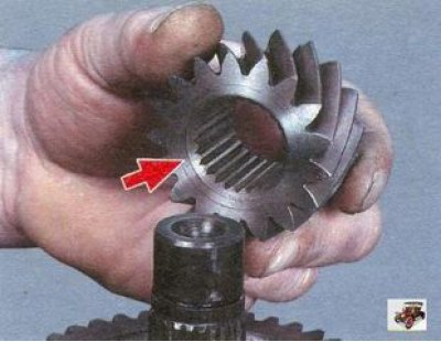
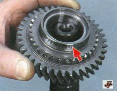
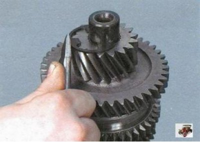
6. Remove the final drive gear from the shaft. Please note that the chamfer on the inside diameter of the gear is directed towards the 1st gear gear.
7. Remove the 1st gear gear from the secondary shaft. The cone on the gear is directed towards the synchronizer.
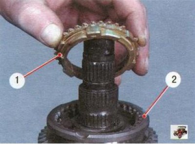
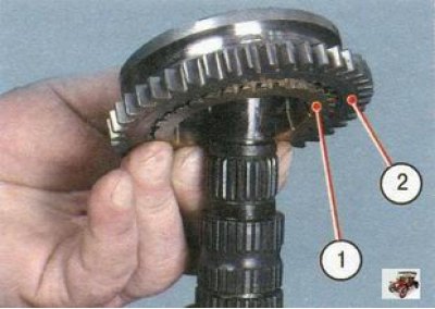
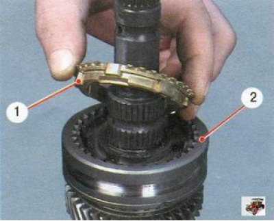
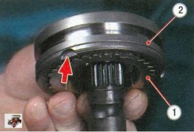
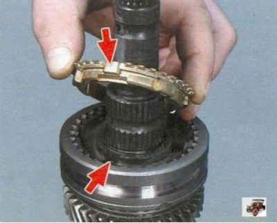
8. Mark blocking ring 1 relative to synchronizer sleeve 2. During operation, the teeth of the ring are run in to the teeth of the coupling, therefore, during assembly, the ring must be installed in the same position. Remove the blocking ring of the 1st gear of the synchronizer.
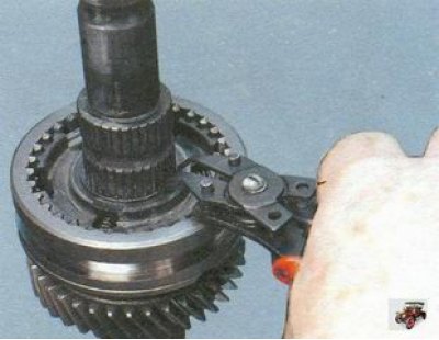
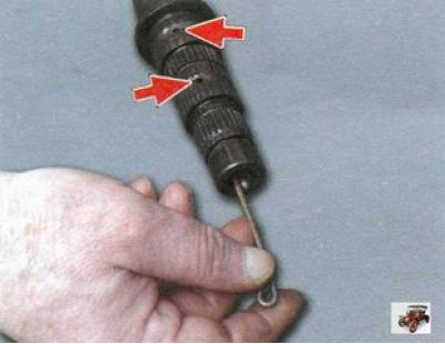
9. Again clamp a secondary shaft of a transmission in a vise and remove a lock ring of a nave of the synchronizer.
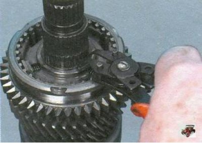
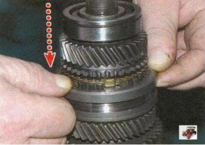
10. Applying force to the 2nd gear gear, use two large screwdrivers to press the 1st-2nd gear synchronizer from the splines of the shaft.
11. Remove the synchronizer with the blocking ring (pos. 1) II gear and mark the ring 1 with respect to the clutch 2 of the synchronizer.
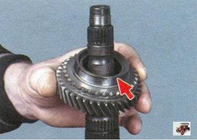
12. Remove the 2nd gear gear from the secondary shaft. Please note that the cone on the gear is directed towards the synchronizer.
13. Turn the output shaft over and use two large screwdrivers to press the rear bearing off the output shaft. The open side of the bearing must face the 4th gear.

14. Remove the thrust washer.
15. Remove the 4th gear. Please note that the cone on the gear is directed towards the synchronizer.
16. Mark blocking ring 1 relative to synchronizer sleeve 2. Remove the blocking ring of the IV synchronizer gear.
17. Remove a lock ring of a nave of the synchronizer.
18. Having unclenched the vice, support the third gear gear on two supports and press the III-IV gear synchronizer from the splines of the secondary shaft with blows of a hammer through a soft gasket.
19. Remove the synchronizer with the third gear blocking ring and mark the ring 1 with respect to the synchronizer clutch 2. Pay attention to the fact that the groove on the clutch is directed towards the 3rd gear gear.
20. Remove the 3rd gear gear. Please note that the cone on the gear is directed towards the synchronizer.
21. Thoroughly clean, rinse and dry the output shaft parts.
22. Check up a condition of a secondary shaft. In the presence of pitting (shells) on the journals for bearings or signs of wear, the output shaft of the gearbox must be replaced.
23. Check the condition of the gears. If there are chips and chipping of the teeth, scuffing in the internal holes or signs of wear on the working surfaces of the teeth, replace the gears. If there is significant crushing or chipping at the ends of the teeth of the spline crown, it is also necessary to replace the gears.
24. Check up ease of rotation of the bearing. If the raceways or balls are damaged, play is detected in the bearing (for reference: the radial clearance in the bearing should not exceed 0.04 mm) replace the bearing.
25. Check up a condition of blocking rings of synchronizers. If there are nicks and chips on the gear rims or significant wear on the cones, replace the blocking rings.
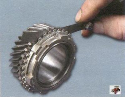
26. Check up a backlash between gear wheels and corresponding blocking rings. To do this, firmly install the blocking ring on the cone of the corresponding gear, that is, after turning several times, «grind» it to the cone, and measure the gap with a flat feeler gauge. The minimum allowable gap is 0.6 mm. If it is less, the blocking ring must be replaced.
Note. When replacing the blocking ring, also check the gap between the new ring and the gear. To do this, put the ring on the gear cone and shake it - play is unacceptable.
27. If scoring and deformation are found on the thrust rings, if their elasticity is lost, replace the retaining rings.
28. Before assembly, clean the oil channels of the secondary shaft.
29. Collect a secondary shaft of a transmission in an order, the return to removal. Install the old blocking rings in accordance with the previously made marks. Install the new blocking rings so that the small protrusions on the ring (missing teeth) coincided with the grooves of the synchronizer hub where the latches are installed.
30. Press in the output shaft rear bearing with a suitable mandrel, applying force only to the inner race of the bearing.
31. Before installing the front bearing inner race, first install the retaining ring and only then press the bearing inner race against the retaining ring with a suitable mandrel.
32. After assembling the secondary shaft, check the operation of the synchronizers. To do this, manually move the synchronizer clutches to the engagement position of the corresponding gears.
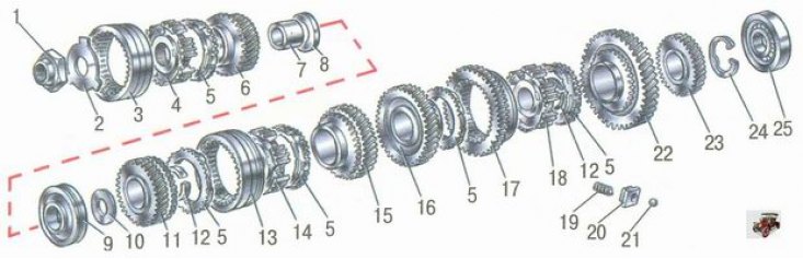
Pic. 5.5. Output shaft details: 1 - nut; 2 - thrust plate; 3 - sliding clutch of the synchronizer of the 5th gear; 4 - sliding clutch hub; 5 - synchronizer blocking ring; 6 - gear V gear; 7 - gear bushing; 8, 10 - thrust washers; 9 - ball bearing; 11 - gear IV gear; 12 - retaining ring of the synchronizer hub; 13 - sliding clutch of the synchronizer of III - IV gears; 14 - sliding clutch hub; 15 - third gear gear; 16 - gear 2nd gear; 17 - sliding clutch of the synchronizer of I - II gears with a gear rim in reverse; 18 - hub of the sliding clutch of the synchronizer of I - II gears; 19 - synchronizer spring; 20 - cracker; 21 - latch; 22 - gear 1st gear; 23 - main gear drive gear; 24 - retaining ring; 25 - cylindrical roller bearing