



When replacing clutch parts, you don't have to remove the gearbox completely (because to do this you need to remove the subframe, which is quite labor-intensive), but only move it away from the engine to the required distance.
Disconnect the terminal from the negative terminal of the battery.
We remove the left wheel drive (see here).
We unscrew the bolt securing the left subframe bracket to the body and loosen the nut securing the bracket to the suspension arm (see here).
Disconnect the clutch cable from the clutch fork and the bracket on the gearbox (see here).
Disconnect the gearbox control rod from the gearbox switch (see here).
We remove the speed sensor.
We remove the crankshaft position sensor.
Disconnect the wiring connector from the reverse light switch.
Disconnect the ECM wiring connector from the oxygen concentration control sensor wiring block.
We remove the sensor block from the holder on the gearbox and take the wiring harness out of the holder.
We remove the starter (see here).
We loosen the holder on the gearbox housing and remove the wiring harness from it. We unscrew the four bolts securing the engine oil pan to the gearbox (see here).
Place adjustable supports under the engine and gearbox. Remove the rear and left supports of the power unit (see here and here).
We disconnect the ground wires from the gearbox, unscrew the bolts and nuts securing the gearbox to the cylinder block (see here).
Holding the housing of the inner joint of the right wheel drive...
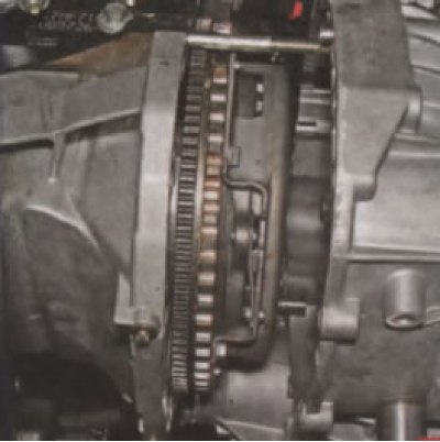
...we move the gearbox away from the engine, removing the primary shaft from the hub of the driven clutch disc.
In this case, the splined shaft of the differential axle gear will come out of the end of the housing of the inner joint of the right wheel drive.
We move the gearbox away from the engine to the required distance and rest the left part of the gearbox on the subframe.
When removing and installing the gearbox, do not rest the gearbox input shaft on the diaphragm spring petals to avoid damaging them.
To replace the clutch release bearing, we move it along the guide sleeve to the end of the gearbox input shaft, disengaging the clutch release fork tabs from engagement with the bearing sleeve.
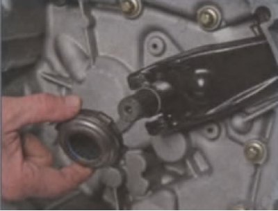
We remove the bearing (for clarity, shown on a removed gearbox).
We remove the fork from the ball joint and remove the end of the fork from the mudguard.
Before installing the bearing, apply plastic grease to the surface of the guide sleeve, the clutch release fork tab, and also to the fork ball joint. We replace the torn rubber cover of the clutch release fork with a new one.
We install the clutch release bearing in the reverse order.
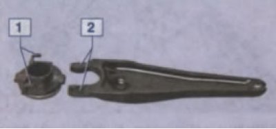
When installing the bearing, the paws 2 of the fork must enter the plastic hooks 1 of the bearing coupling.
Further, the operations for replacing the clutch discs are similar to replacing them with the gearbox removed (see here).