



Removal of the right drive is shown here.
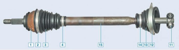
Left-hand drive vehicles with JH3 gearbox: 1 - outer CV joint housing; 2 - large clamp of the outer CV joint boot; 3 - outer boot; 4 - small clamp of the outer joint boot; 11 - inner CV joint tripod; 12 - holder of the inner CV joint boot of the left wheel drive; 13 - boot of the inner CV joint of the left wheel drive; 14- clamp for fastening the boot of the inner CV joint of the left wheel drive; 15 - left wheel drive shaft
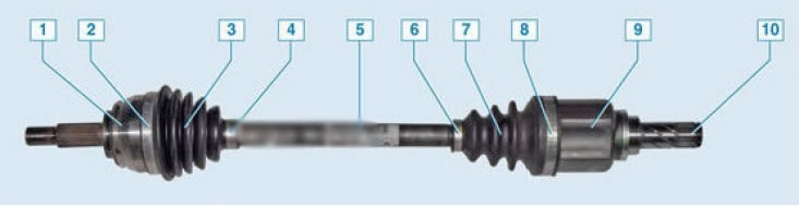
Left-hand drive vehicles with JR5 gearbox: 1 – outer CV joint housing; 2 – large clamp of the outer CV joint boot; 3 – outer CV joint boot; 4 – small clamp of outer CV joint boot; 5 – left drive shaft; 6 – small clamp of the inner CV joint boot; 7 – anther; 8 – large clamp of the inner CV joint boot; 9 – inner CV joint housing; 10 – retaining ring
Removal
Place the vehicle on a two-post lift, apply the parking brake, turn off the ignition, open the hood and disconnect the ground wire from the battery.
Remove the left front wheel.
Remove the engine crankcase guard.
Unscrew the drain plug in the gearbox housing and drain the oil (1/2 inch internal square key, technological container).
Disconnect the connector and remove sensor 1, Figure 12-1, left front wheel speed sensor (if available).
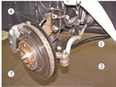
Figure 12-1 - Removing the left front wheel drive: 1 - Left front wheel speed sensor; 2 - nut for fastening the ball joint pin of the steering rod end; 3 - hub nut; 4 - nut of the bolt securing the steering knuckle to the front suspension strut
Place a stop on the hub of the left front wheel and secure it with two wheel bolts (stop Rou. 604-01, replaceable head 17, ratchet).
Unscrew nut 3 securing the left front wheel hub, remove the nut, and remove the stop. The front wheel hub mounting nut needs to be replaced (replacement head 30, Replacement head 17, Ratchet).
Loosen nut 2 securing the ball joint pin of the outer end of the steering rod and press the pin out of the steering knuckle arm (replacement head 16, ratchet, Tav. 476 device).
Loosen and remove bolts 1, Figure 12-2, securing guide 2 of the front left brake to the steering knuckle (replacement head 18, extension, ratchet).
Remove and hang the front brake guide assembly with brake pads and caliper 4 to the front suspension spring to avoid loading the brake hose (technological hook).
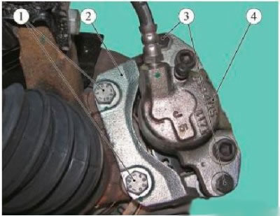
Figure 12-2 - Removing the front brake guide: 1 - front brake guide mounting bolts; 2 - front brake guide; 3 - guide pin mounting bolts; 4 - support
Loosen the two nuts 4, Figure 12-1, of the bolts securing the left steering knuckle to the front suspension strut and remove the bolts (spanner 18, replaceable head 18, ratchet).
If necessary, press out the splined tailpiece of the outer joint of the left front wheel drive from the hub using tools (tav. 1420-01 and Tav. 1050-04 devices).
Tilt the steering knuckle and remove the splined tailpiece of the outer joint of the left front wheel drive from the hub.
Secure the steering knuckle to the front suspension strut with a bolt.
For vehicles with JH3 gearbox
Loosen the three bolts 1, Figure 12-3, securing the protective cover holder 2 of the inner hinge of the left front wheel drive (replacement head 13, extension, ratchet).
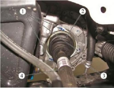
Figure 12-3 - Removing the left front wheel drive on a vehicle with a JH3 transmission: 1 - protective cover holder mounting bolt; 2 - protective cover of the inner joint of the left front wheel drive; 3 - gearbox; 4 - left front wheel drive
Remove the tailstock of the 4th left front wheel drive shaft from the tripod joint of the 3rd gearbox.
For vehicles with JR5 gearbox
Remove the inner joint of the drive 1, Fig. 12-4, of the left front wheel from the half-axle gear of the gearbox 2 using tool 3 or 67.7801-9524 (tav. 1744 device for removing the left front wheel drive or device for dismantling the wheel drive 67.7801-9524).
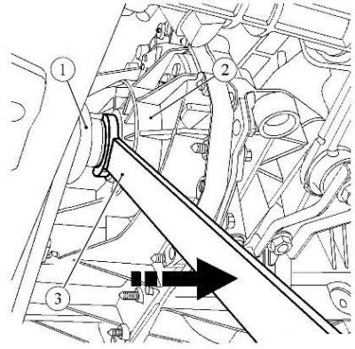
Figure 12-4 - Removing the left front wheel drive on a vehicle with a JR5 transmission: 1 - left front wheel drive; 2 - gearbox; 3 - Tav. 1744 device for removing the left front wheel drive
Remove the left gearbox differential seal.
Installation
For vehicles with JH3 gearbox
Install the drive shaft 4, Figure 12-3, of the left front wheel into the tripod joint of the 3rd gearbox.
Install the outer joint tailpiece of the left front wheel drive into the wheel hub.
Install three bolts 1 securing the holder of the protective cover 2 of the inner joint of the left front wheel drive to the gearbox 3. Tightening torque of the bolts securing the holder of the protective cover of the inner joint of the left front wheel drive 25 N·m (2.5 kgf·m) (replaceable head 13, extension, ratchet, torque wrench).
For vehicles with JR5 gearbox
Check the condition of the left differential seal seat in the gearbox housing.
(Material was taken from the website: ladaman)
Install a new left gearbox differential seal.
Remove the retaining ring 1, Figure 12-5, from the groove of the inner joint shaft 2 of the front wheel drive and install a new ring. Reuse of the retaining ring is not permitted (flat head screwdriver).
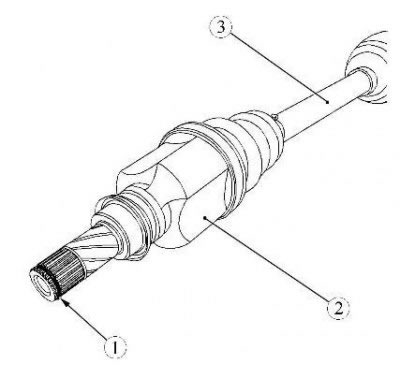
Figure 12-5 - Installing the left front wheel drive on a vehicle with a JR5 transmission: 1 - retaining ring; 2 - inner joint of the left front wheel drive; 3 - left front wheel drive shaft
Install the splined part of the inner joint 2 of the left front wheel drive into the splines of the differential axle gear as coaxially as possible so as not to damage the seal.
Make sure that the drive is fixed in the axle shaft gear using your hands, applying a load to the inner joint towards the steering knuckle.
Install the splined tail of the outer joint of the left front wheel drive into the wheel hub.
Operations for all vehicle configurations
Install the left steering knuckle onto the front suspension strut.
Install two bolts securing the steering knuckle to the front suspension strut and tighten nuts 4, Figure 12-1, of the securing bolts. Tightening torque of the steering knuckle mounting bolts nuts 105 Nm (10.5 kgf·m) (spanner 18, replaceable head 18, ratchet, torque wrench).
Attention! After removal, bolts 1, Figure 12-2, securing the guide to the steering knuckle must be replaced, since the bolts are fixed with an adhesive compound applied to the threaded surface of the bolts. Reuse of bolts is not permitted.
Install the left guide 2 of the front brake on the steering knuckle and secure it with new mounting bolts. First apply "HIGH-STRENGTH LOCKING COMPOUND" to the threaded surface of the bolts in the amount of 1 g per bolt. Tightening torque of bolts 105 Nm (10.5 kgf·m) (replaceable head 18, extension, ratchet, torque wrench, "HIGH-STRENGTH LOCKING COMPOSITION" 77 11 230 112).
Install the ball joint pin of the left steering rod end into the steering knuckle arm and tighten nut 2, Figure 12-1, of the fastening. Tightening torque of the nut for fastening the ball joint pin of the steering rod end 37 N·m (3.7 kgf·m) (replaceable head 16, ratchet, torque wrench).
Place a stop on the front wheel hub and secure it with two wheel bolts (stop Rou. 604-01, replaceable head 17, ratchet).
Install a new 3 wheel hub nut. Wheel hub nut tightening torque 280 Nm (28.0 kgf·m) (replaceable head 32, ratchet, torque wrench).
Loosen the two wheel bolts and remove the stop from the front wheel hub (stop Rou. 604-01, replaceable head 17, ratchet).
Connect and secure the left front wheel speed sensor 1 (if available).
Install a new transmission drain plug gasket.
Install the drain plug into the gearbox housing and tighten to 22 N·m (2.2 kgf·m) (1/2 inch internal square wrench, torque wrench).
Unscrew the filler plug, pour oil into the gearbox and screw the plug back on. The oil level should be at the lower edge of the filler hole (filling unit for transmission oils of type C-223-1, transmission oil according to the current "Codifier of the main and auxiliary materials used in the maintenance and repair of LADA K vehicles" 3100.25100.00018, oil consumption rate: for the JH3 gearbox - 2.8 l; for JR5 gearbox - 2.5 l).
Install the engine oil pan guard.
Install the left front wheel.