



Note: Replacing the dust cover (without special devices) shown also in section Replacement of CV joints.
Removal
Remove the front wheel drive (see left hand drive or right hand drive).
Install the front wheel drive with the middle part of shaft 1, figures 13-2 and 13-3, in a vise (a locksmith's vise with aluminum linings, a locksmith's workbench of the SHP-17 "GARO" type).
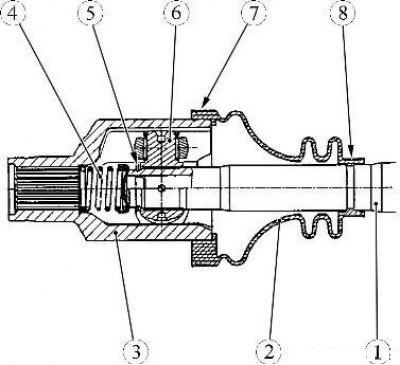
Figure 13-2 - Removing the front wheel drive inner joint boot for the JH3 transmission: 1 - wheel drive shaft; 2 - protective cover; 3 - inner hinge housing; 4 - spring; 5 - retaining ring; 6 - three-pin hinge; 7 - large clamp; 8 - small clamp
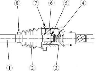
Figure 13-3 - Removing the front wheel drive inner joint boot for the JR5 transmission: 1 - wheel drive shaft; 2 - protective cover; 3 - inner hinge housing; 4 - spring; 5 - retaining ring; 6 - three-pin hinge; 7 - large clamp; 8 - small clamp
(Article copied from the resource: LADAMAN.ru)
Cut off the large 7 and small 8 clamping clamps using nippers, trying to damage the housing 3 of the outer hinge and the shaft 1 of the drive (nippers).
Cut cover 2 along its entire length and remove it from the shaft (technological knife).
Remove grease (technological spatula, rags).
Mark the relative position of the housing 3 of the inner hinge of the front wheel drive, the three-pin hinge 6 and the shaft 1 of the drive by any method except mechanical.
Remove the housing 1, Figure 13-4, of the inner joint from the drive shaft 2. There is no lock on the housing of the inner joint, it can be removed without applying force.
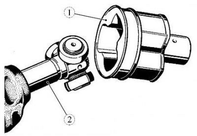
Figure 13-4 - Removing the front wheel drive inner joint: 1 - inner hinge housing; 2 - wheel drive shaft
Remove retaining ring 1, Fig. 13-5 (external snap ring pliers).
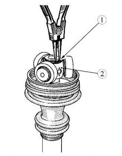
Figure 13-5 - Removing the front wheel drive inner joint retaining ring: 1 - retaining ring; 2 - three-pin hinge
Press the three-pin joint 1, Figure 13-6, with a press, using puller 2 as a stop (hydraulic press type KS-124, puller type 71 03 00 01 f. "Stahlwille").
Attention! Do not remove the rollers from the hinge pins, as the rollers and bearing needles are worn to each other and should not be swapped.
Wash the drive parts and blow them with compressed air (high-pressure washing unit with water heating type HDS 895 S "Karcher" (Germany), gun type AH 050101 "ANI" (Italy) for blowing with compressed air).
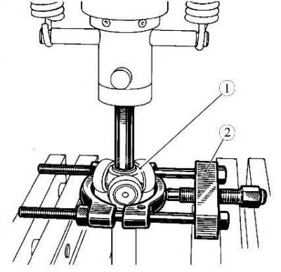
Figure 13-6 - Removing the front wheel drive three-pin joint: 1 - three-pin hinge; 2 - puller
Installation
Install the front wheel drive shaft with the middle part in a vise (a locksmith's vise with aluminum linings, a locksmith's workbench of the SHP-17 "GARO" type).
Front wheel drive parts that must be replaced:
- protective cover of the inner joint of the drive shaft of the right front wheel;
- retaining ring;
- spring cup;
- spring;
- small clamp;
- large clamp.
Place clamp 8, Figures 13-2 and 13-3, of small diameter on shaft 1 of the wheel drive.
To facilitate installation of the protective cover, lubricate the wheel drive shaft (grease for front wheel drive shaft joints 77 11 420 011 according to the current "Codifier of main and auxiliary materials used in maintenance and repair of LADA vehicles" K 3100.25100.00018, technological blade).
Install the protective cover 2 of the inner joint on the drive shaft.
Press the three-pin joint 6 onto the drive shaft. When assembling, ensure that the marks applied before disassembly match (plastic-head hammer).
Install a new retaining ring 5 on the drive shaft (external snap ring pliers).
Install the cup with spring 4 into the inner hinge housing 3.
Install the inner joint housing onto the drive joint.
Fill the cavity of the inner joint housing and the protective cover with grease for front wheel drive shaft joints in equal quantities (grease for front wheel drive shaft joints 77 11 420 011 according to the current "Codifier of main and auxiliary materials used in maintenance and repair of LADA vehicles" K 3100.25100.00018, technological blade).
Place the edges of the cover in the grooves of the hinge housing and the wheel drive shaft (flat head screwdriver).
Insert a rod with rounded edges between the boot and the hinge body to adjust the amount of air inside the hinge (technological rod).
Rock the CV joint manually to check that the boot belts are installed correctly.
Install small 8 and large 7 clamps on the protective cover of the inner joint of the right front wheel drive shaft.
Tighten the small and large clamps until they click using the tool (device for installing clamps Tav. 1168 or Tav. 1256, or Tav. 1784 depending on the design of the clamp).
Install the front wheel drive shaft.