
Car repair AvtoVAZ Car repair Renault Car repair Hyundai Car repair Ford Car repair Volkswagen Car repair Audi Car repair Chevrolet
English Русский
Български
Беларускі
Український
Српски
Hrvatski
Română
Polski
Slovenský
Magyar
articles sitemap contacts bookmark
LadaMan.ru


Kalina Granta Priora Vesta Largus XRAY
Largus 1 (2012-2023)

Disassembling the right inner CV joint of a car with a JH3 gearbox (Largus 1)

  • Main
  • Largus
  • Largus 1
  • Transmission
  • Drive shafts
  • Disassembling the right inner CV joint of a car with a JH3 gearbox
0
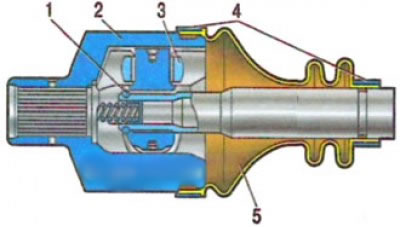
Right inner CV joint of a car with a JH3 gearbox: 1 - retaining ring; 2 - hinge housing; 3 -…

Right inner CV joint of a car with a JH3 gearbox: 1 - retaining ring; 2 - hinge housing; 3 - three-spike hub roller; 4 - boot clamps; 5 - anther


Please do the following:
Please do the following:


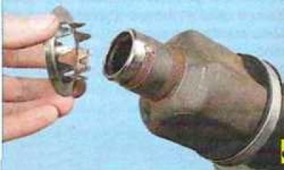
1. Remove the mud-deflecting washer from the CV joint housing tailpiece.
1. Remove the mud-deflecting washer from the CV joint housing tailpiece.


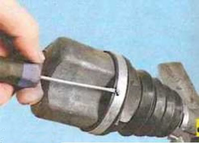
2. Remove the large boot mounting clamp by bending its end with a screwdriver...


2. Remove the large boot mounting clamp by bending its end with a screwdriver...


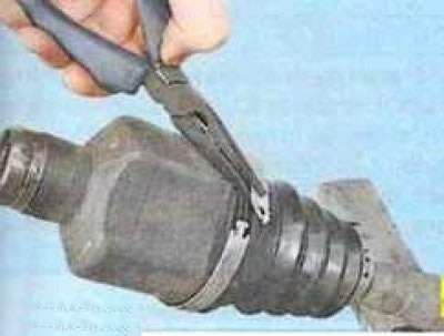
3. ...and grasping the clamp with thin-nosed pliers.
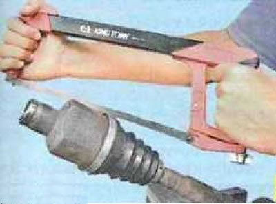
3. ...and grasping the clamp with thin-nosed pliers.


The clamp can be cut with a hacksaw, since the old clamp cannot be reinstalled. When cutting the clamp, be careful not to damage the groove for the boot on the CV joint housing.

4. Remove the small boot mounting clamp in the same way.
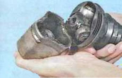
4. Remove the small boot mounting clamp in the same way.


5. Remove the hinge housing.
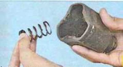


5. Remove the hinge housing.


6. Remove the spacer spring from the housing...
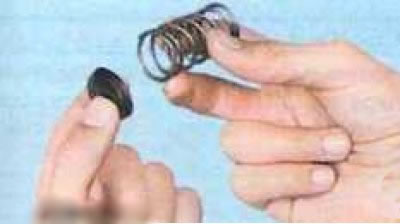
6. Remove the spacer spring from the housing...


7. ...together with the thrust washer.
7. ...together with the thrust washer.


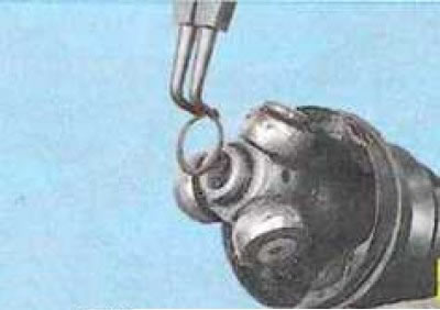
8. Remove the CV joint hub retaining ring by spreading it with a retaining ring plier or round-nose pliers.
8. Remove the CV joint hub retaining ring by spreading it with a retaining ring plier or round-nose…


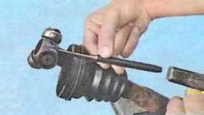
9. Slide the hub with rollers along the shaft splines...


9. Slide the hub with rollers along the shaft splines...


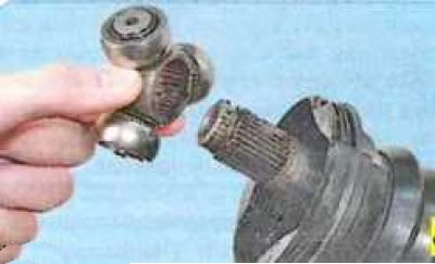
10. ...and remove it from the shaft.
10. ...and remove it from the shaft.


Mark the position of the hub relative to the shaft and install it according to the marks during assembly. If you are installing a new hub, orient it according to the marks on the old hub.

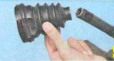
11. Remove the boot from the drive.
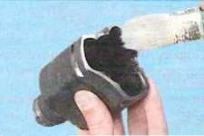
11. Remove the boot from the drive.


12. If the CV joint was disassembled only to replace the boot, remove the old grease from it by washing the internal cavity with kerosene or gasoline
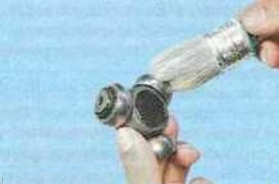


12. If the CV joint was disassembled only to replace the boot, remove the old grease from it by…


13. ...and the hub. Dry the parts with compressed air.

Note: If the boot is not torn, then it is not necessary to wash it - it is enough to thoroughly remove the old grease with a cleaning material.


14. Install a new dust cover on the drive shaft. Make sure that the annular protrusion on the inner surface of the boot in the area of the small diameter belt fits into the groove on the shaft.
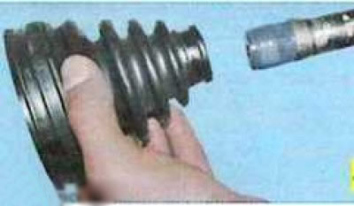
14. Install a new dust cover on the drive shaft. Make sure that the annular protrusion on the inner…


To avoid damaging the joint boot during assembly, wrap the splined portion of the shaft with electrical tape.

To facilitate installation of the boot, lubricate the shaft with a thin layer of grease intended for filling the joint.

15. Press the joint hub assembly with rollers onto the shaft splines (a suitable tool head can be used as a mandrel), align the marks made during disassembly and install the retaining ring (see item 8), making sure that the ring is completely inserted into the groove of the shaft.
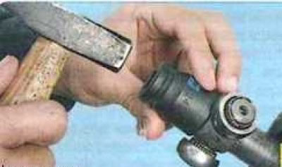


15. Press the joint hub assembly with rollers onto the shaft splines (a suitable tool head can be…


16. Place half of the required amount of MOBIL CVJ 825 BLACK STAR grease into the boot, the total amount of grease is (124±10 g). Place the remaining grease evenly into the cavity of the joint housing.

Do not reduce or increase the recommended amount of grease in the joint.

17. Install the spacer spring and thrust washer into the cavity of the hinge housing (see points 6 and 7).

18. Install the housing on the rollers of the three-spike hub and put the dust cover on the housing. Make sure that the annular protrusion on the inner surface of the boot in the area of the large diameter belt fits into the groove on the CV joint housing.

19. Remove excess air from the boot by lifting the large edge of the boot and inserting a thin, blunt tool underneath it.

20. Without removing the tool from under the edge of the boot, move the CV joint parts so that the distance between the ends of the small belt of the boot and the tail of the CV joint housing is 190 mm.

If excess air is not removed from under the boot and the required joint length is not set before securing the boot with clamps, the boot may be damaged during operation.

21. Without changing the position of the hinge parts, remove the tool from under the edge of the boot and secure the boot with clamps.
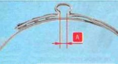
21. Without changing the position of the hinge parts, remove the tool from under the edge of the…


The criterion for correct compression of the ear clamp is the gap A. It should be 2.4-2.8 mm. If the gap is larger, "tighten" the clamp to the norm; if less, replace the clamp.

22. Install a mudguard washer onto the hinge housing tailstock.


This article is available at russian, bulgarian, belarusian, ukrainian, serbian, croatian, romanian, polish, slovak, hungarian
This article has been reviewed: Daniil Markelov
Share with friends:
◀ Previous
Lada Largus 1: Drive shafts
Next ▶

Disassembling the left inner CV joint of a car with a JH3 gearbox
Replacing outer and inner CV joints (JR5)
Replacing the left inner CV joint boot
Replacing the right inner CV joint boot
Replacing the outer joint boot of the front wheel drive
Replacing outer CV joint boots on a car with a JH3 gearbox
Replacing the outer CV joint and boot of a car with a JR5 gearbox
More articles with information from manuals for Lada:

• Reference data on gearbox components Lada Kalina Hatchback (2004-2013, VAZ-1119)
• Gearbox Reference Data Lada Granta 1 (2011-2023, VAZ-2190)
• Disassembling the gearbox and identifying its parts Lada Priora 1 (2007-2018, VAZ-2170)
• Manual gearbox — technical condition check Lada Vesta 1 (2015-2023, VAZ-2180)
• Troubleshooting the gearbox Lada X-Ray 1 (2015-2022)
Link to this article in various formats
Reviews and comments of visitors
No comments yet


Add up two numbers: 31 + 10


Largus 1 (2012-2023) 
  • General information
  • Vehicle device
  • User manual
  • Maintenance
  • Power unit
  • Engine repair
  • Cooling and lubrication system
  • Supply system
  • Ignition system
  • Exhaust system
  • Spare parts catalog
  • Transmission
  • Clutch
  • Car gearbox
  • Drive shafts
  • Spare parts catalog
  • Chassis (running gear)
  • Suspension and wheels
  • Steering
  • Brake system
  • Spare parts catalog
  • Body and interior
  • Exterior (external elements)
  • Interior (internal elements)
  • Doors, locks and windows
  • Heating and ventilation
  • Spare parts catalog
  • Electrical equipment
  • Equipment and devices
  • Power devices
  • Lighting and signaling
  • Spare parts catalog
  • Electrical circuits
LadaMan.ru © 2018–2026 | Mobile version | About Lada | Sitemap: EN BG BY UA RS HR RO PL SK HU | Contacts with admin | | Add to bookmarks
Kalina Hatchback (2004-2013) | Kalina Sedan (2004-2013) | Granta 1 (2011-2023) | Priora 1 (2007-2018) | Vesta 1 (2015-2023) | Largus 1 (2012-2023) | X-Ray 1 (2015-2022) |
This site uses cookies to ensure everything runs smoothly.