



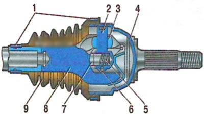
Outer CV joint of a car with a JH3 gearbox: 1 - cover fastening clamps; 2 - three-spike hub; 3 - roller; 4 - hinge housing; 5 - spring; 6 - adjusting spacer; 7 - pusher; 8 - drive shaft; 9 - hinge cover
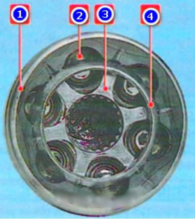
Outer joint type Birfield (gearbox JR5): 1 - body, 2 - six balls, 3 - cage, 4 - separator
1. Remove the inner CV joints and their boots from the drives (see above). And when replacing the boot of the left drive, press the bearing assembly with the seal and mud deflector off the shaft, as described above.
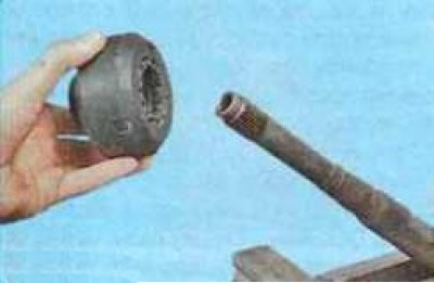
2. When replacing the outer right CV joint boot, additionally remove the dynamic damper from the shaft, overcoming the elastic resistance of the rubber mass of the damper.
Before removing the rubber dynamic damper, measure and remember the distance between the edges of the damper and the boot so that you can install the part in its original position during assembly.
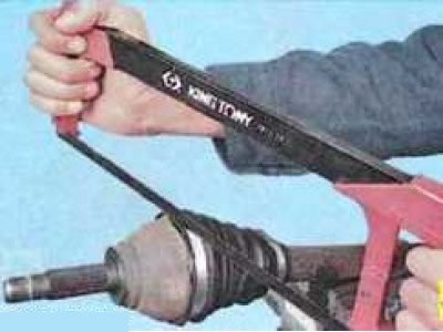
3. Remove the large...
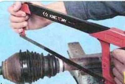
4. ...and the small boot clamps, cut with a hacksaw for metal.
When cutting the clamps, be careful not to damage the edges of the grooves for the boot on the hinge housing and the drive shaft.
5. Remove the boot by pulling it along the shaft.
To avoid damage to the joint during operation, after removing the boot, do not separate the CV joint housing and the drive shaft.
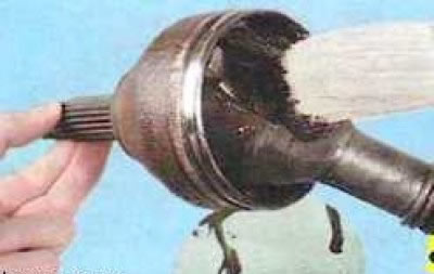
6. Remove old grease from the joint by washing its cavity with gasoline or kerosene, and dry the joint with compressed air.
Do not use solvents to clean the joint.
7. Install a new boot on the drive. Make sure that the annular protrusion on the inner surface of the boot in the area of the small diameter belt fits into the groove on the shaft.
To facilitate pulling the boot along the drive shaft and to prevent contamination of the joint cavity, thoroughly clean the shaft from dirt and rust with fine-grained sandpaper and lubricate with a thin layer of grease intended for filling the joint.
8. Place half of the required amount of MOBIL CVJ 825 BLACK STAR grease into the boot; the total amount of grease is (294±10) g. Place the remaining grease evenly into the cavity of the joint housing.
Do not reduce or increase the recommended amount of grease in the joint.
9. Put the boot on the CV joint. Make sure that the annular protrusion on the inner surface of the boot in the area of the large diameter belt fits into the groove on the CV joint body.
10. Remove excess air from the boot by lifting the large edge of the boot and inserting a suitable thin tool underneath it.
If excess air is not removed from under the boot, it may be damaged during operation.
11. Remove the tool from under the edge of the boot and secure the boot with clamps.
12. For the right drive, install the dynamic damper on the shaft, maintaining the distance measured before disassembly between the damper and the boot.
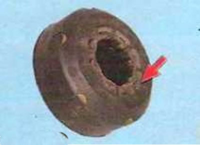
Install the dynamic damper on the shaft, orienting its end without the flange towards the outer CV joint.
13. Install all inner CV joint parts onto the shaft.
To increase the service life of the inner CV joint, replace the grease in it with new grease as a preventative measure.