



Attention! If during the gearbox repair process at least one of the following parts was replaced: clutch or gearbox housing, differential housing or differential bearings, then it is necessary to select an adjusting ring for the differential bearings.
You will need: a socket wrench (head) "10", "13", "32", wrenches "10" and "17", a large screwdriver, a punch, a hammer, pliers for removing retaining rings, an impact screwdriver.
1. Remove the gearbox from the vehicle (see "Removal and installation of the gearbox"). Clean it from dirt and wash the outside.
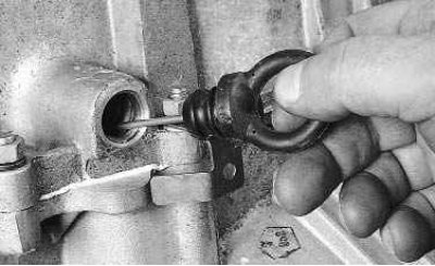
2. Remove the oil level indicator (dipstick) from the gearbox.
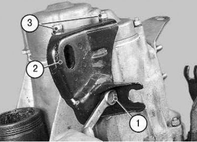
3. Install the gearbox on the clutch housing vertically, use a 10 mm wrench to unscrew bolt 1 (a flat washer is installed under its head) and two nuts 3 (spring washers are installed underneath them) clutch cable bracket fastenings. Remove the clutch cable bracket 2 from the gearbox.
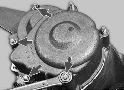
4. Using a 10 mm spanner, unscrew the remaining four nuts securing the rear cover.
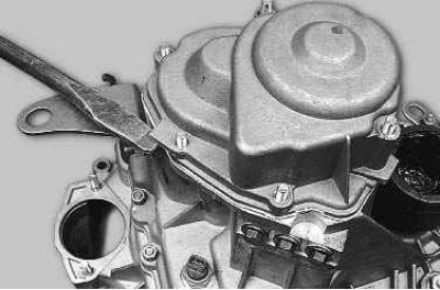
5. Using a screwdriver, pry up the lug on the cover and remove the back cover.
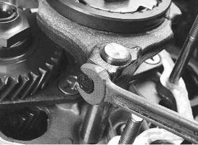
6. Using a 10 mm spanner, unscrew the 5th gear fork mounting bolt (a spring washer is installed under the bolt head).
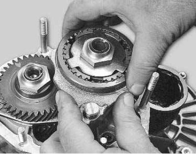
7. Secure the gearbox shafts from turning. To do this, engage 5th gear by moving the synchronizer clutch down together with the fork so that the clutch splines engage with the gear, then engage 3rd or 4th gear by moving the gear selection rod.
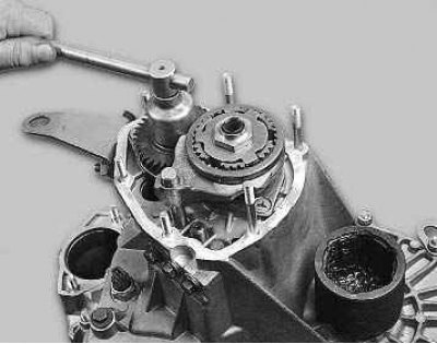
8. Unlock and use a 32 mm head to unscrew the primary shaft mounting nut. To do this, you need to apply a lot of force, since the nut is tightened with a high torque.
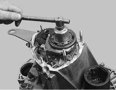
9. Having previously released the lock, use a 32 mm head to unscrew the secondary shaft mounting nut. To do this, you need to apply force, since the nut is tightened with a high torque.
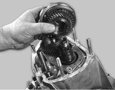
10. Using screwdrivers, lift the driven gear of the 5th gear (thereby pressing the synchronizer hub off the shaft), remove it together with the synchronizer and fork from the secondary shaft.
Caution: Be careful not to let the synchronizer sleeve come off the hub, as the spring-loaded synchronizer locking balls may fall apart.
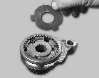
11. Remove the thrust plate from the synchronizer. Then remove the fork from the synchronizer clutch groove.
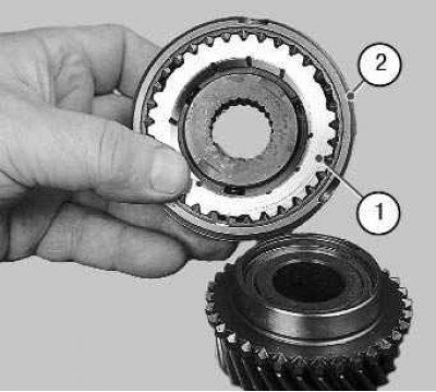
12. Remove the 5th gear from the synchronizer with blocking ring 1. Mark blocking ring 1 relative to clutch 2 and remove it. During operation, the teeth of the ring become accustomed to the teeth of the coupling, therefore, during assembly, the ring must be installed in the same position. If you do not intend to disassemble the synchronizer, tie it with wire or rope to prevent it from falling apart.
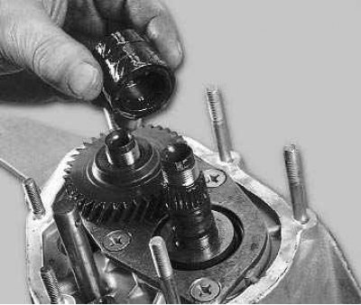
13. Remove the sleeve from the secondary shaft.
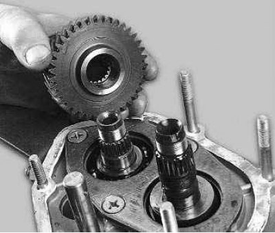
14. Remove the drive pinion from the input shaft. Notice how it is installed.
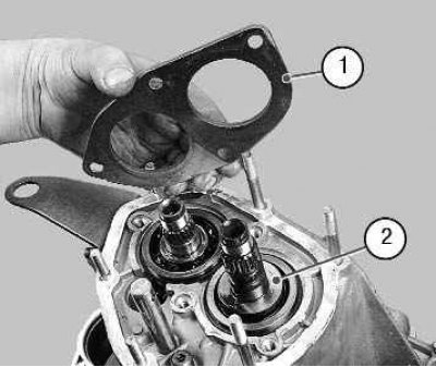
15. Using an impact screwdriver, remove the four screws (spring washers are installed underneath them) bearing plate fasteners and remove bearing plate 1. Then remove thrust washer 2 from the secondary shaft.
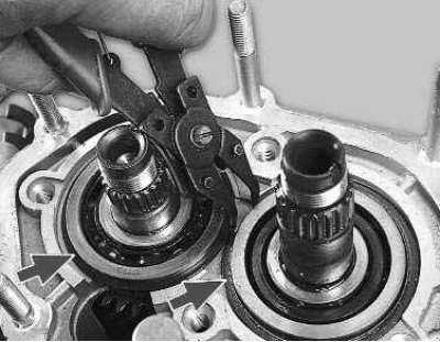
16. Remove the bearing retaining rings from both shafts by lifting the shafts by hand.
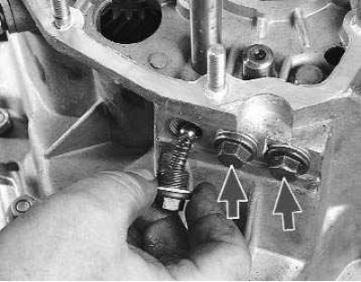
17. Using a 13 mm spanner, unscrew the three retainer plugs and carefully remove the retainer balls with springs.
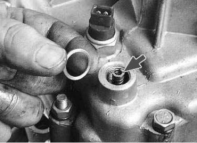
18. After unscrewing the reverse lock plug, remove the sealing ring, and then remove the lock spring.
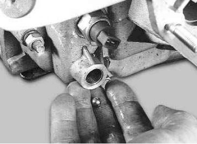
19. Tilt the box and remove the retainer ball.
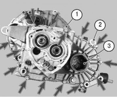
20. Unscrew the twelve nuts and remove the gearbox housing mounting bolt. Pay attention to the nuts under which the holder 1 and the transport eye 2 are installed. Spring washers are installed under the nuts and bolt. Remove plug 3 inserted in place of one of the drives.
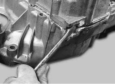
21. Inserting a screwdriver into the grooves (three special grooves along the perimeter of the housings), separate the gearbox housing from the clutch housing.
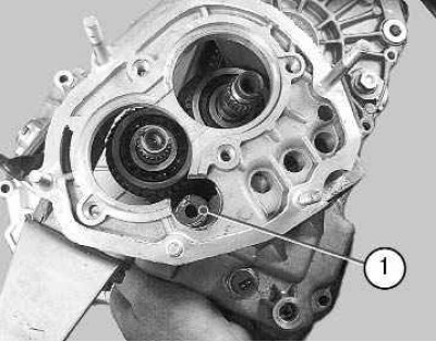
22. Raise the gearbox housing slightly, turn it counterclockwise so that the lug 1 of the housing comes out from under the gear, and remove the gearbox housing from the clutch housing.
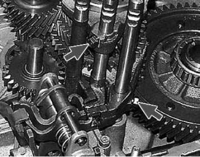
23. Using a 10 mm spanner, unscrew the bolts securing the shift forks for 1st and 2nd, 3rd and 4th gears.
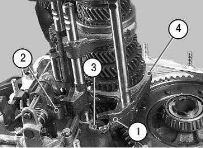
24. Slightly lift the 1st and 2nd gear shift rod so that it comes out of support 3, and turn it counterclockwise so that head 1 of the rod comes out of engagement with locking bracket 2. Remove fork 4 of the rod from the groove of the synchronizer clutch and remove the rod with the fork. It is not recommended to remove the forks from the rods unless necessary, so as not to mix them up during assembly.
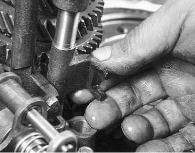
25. Turn the III and IV gear shift rod and disengage its head from the gear selection lever. Then lift the rod slightly so that it comes out of the support, and, having removed the rod fork from the groove of the synchronizer clutch, remove the rod with the fork.
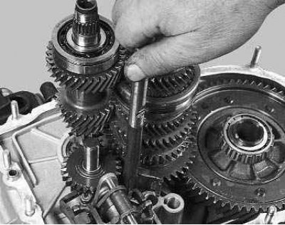
26. Turn the 5th gear engagement rod and disengage its head from the locking bracket. Remove the rod by pulling it out of the support.
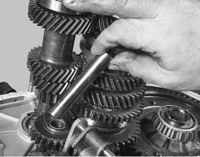
27. Remove the reverse intermediate gear shaft.

28. Move the reverse intermediate gear until it stops in the gear selection mechanism, turn it 30–40° and, removing it from under the shaft gears, remove the intermediate gear.
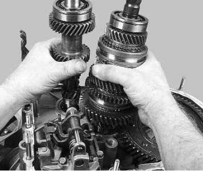
29. While rocking slightly, remove the primary and secondary shafts simultaneously.
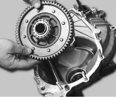
30. Remove the differential from the clutch housing.
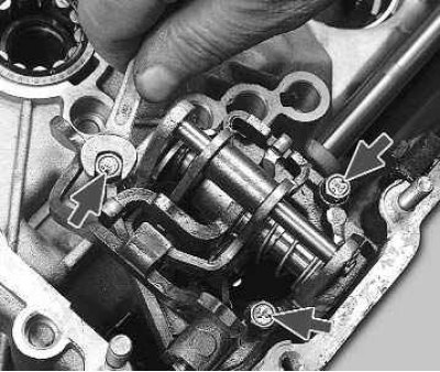
31. Using a 10 mm spanner, unscrew the three bolts securing the gear selection mechanism (spring washers are installed under the bolt heads). Remove the gear selector mechanism.
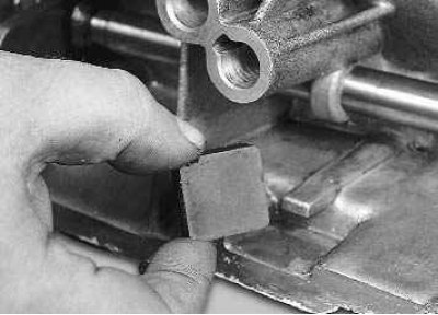
32. Remove the magnet from the clutch housing.
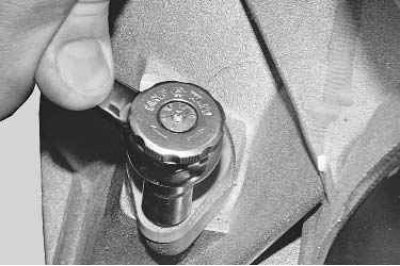
33. Using a 10 mm spanner, unscrew the speed sensor mounting nut and remove the sensor.
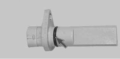
34. Replace the torn or loose speed sensor sealing ring.
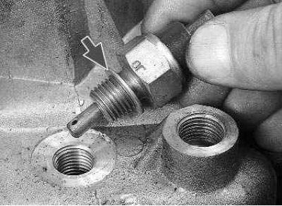
35. Unscrew the reverse light switch from the gearbox housing. There is a metal sealing ring installed underneath it.
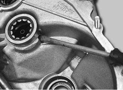
36. There is a special puller for pressing out the front bearing of the secondary shaft. If it is missing, press out the bearing using a screwdriver.
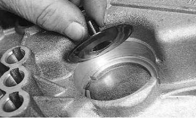
37. Remove the oil pan installed under the bearing.
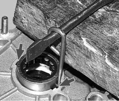
38. There is also a special puller for pressing out the front bearing of the primary shaft. If you don't have one, make a hook-shaped device out of stiff wire. Insert the tool into one of the two slots in the crankcase and slide the hook under the bearing. Then using a screwdriver (putting a wooden block underneath) press the bearing out of the housing by applying force to the opposite end of the screwdriver with hammer blows and alternately moving the hook in the grooves.
39. Press the new front shaft bearings into the clutch housing until they stop, using a suitable mandrel.
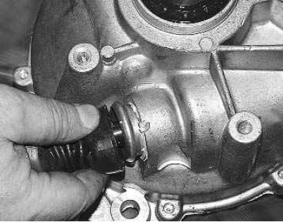
40. Use a screwdriver to pry up the edge of the gear selector rod protective cover and slide it off the rod support sleeve.
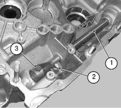
41. Using a 10 mm spanner, unscrew bolt 3 securing gear selection lever 2. After moving rod 1, remove the gear selection lever. Then remove the gear selector rod from the clutch housing.
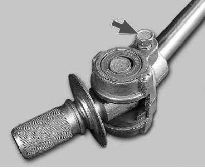
42. If it is necessary to replace the rod hinge, slide the protective cover off it and unscrew the hinge mounting bolt. The bolt is fixed with special glue TB-1324. Before screwing in the bolt, clean it from old glue and apply new one. Replace the torn or loosened piston rod joint protective boot.
43. To replace the clutch housing, remove the bearing from it (see "Replacing the clutch release bearing") and the clutch release fork (see "Replacing the clutch release fork"), press out the seals (see "Replacing gearbox seals").
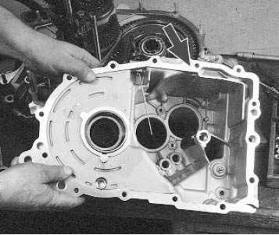
44. Inspect the clutch and gearbox housings, as well as the rear cover. They should not have any cracks or chips. There should be no nicks, scratches, dents, etc. on the mating surfaces. Remove minor damage with sandpaper. In case of severe damage, replace defective parts.
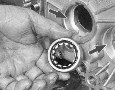
45. Check the bearing seats in the clutch and gearbox housings. These surfaces must not show any signs of wear or damage. Otherwise, replace the crankcases.
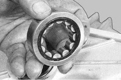
46. Check the condition of the roller bearings. If the raceways, separator or rollers are damaged and if play is detected (the radial clearance in the bearing should not exceed 0.07 mm) replace the bearing.
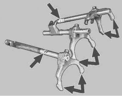
47. Check the condition of the gear shift rods. Replace bent rods, those with burrs, nicks or worn-out dimples for the clamps. Replace the forks if they are bent or their tabs are worn.
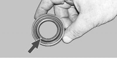
48. Check the axle shaft seals. They should not be warped or have tears. The working edge must be smooth, without any dents, dents or rubber build-up. The oil seal spring must not be broken or stretched. Replace defective seals.
49. Check and, if necessary, replace the primary shaft and gear selector rod seals (see "Replacing gearbox seals").
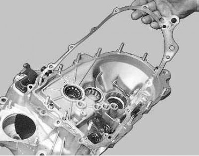
50. Replace damaged or heavily compressed gaskets.
51. Clean the magnet from wear particles. If the magnet becomes cracked or its magnetic properties become weak, replace the magnet.
52. Carefully clean the mating surfaces of the clutch and gearbox housings, as well as the rear cover, from old sealant.
53. Assemble the gearbox in the reverse order of disassembly, taking into account the following.
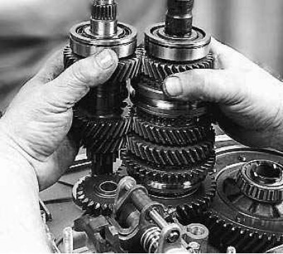
54. Before installing the shafts, engage the teeth of their gears and install them in the clutch housing in this position.
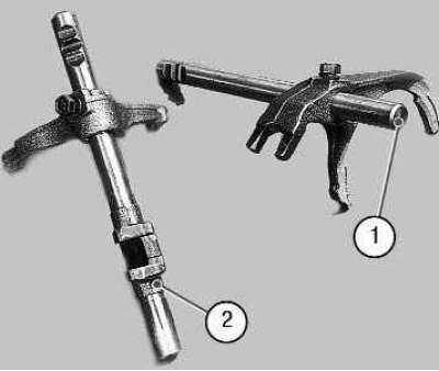
55. Pay attention to how the forks are installed on the gear shift rods: 1 – rod with a fork for shifting 1st and 2nd gears, 2 – rod with a fork for shifting 3rd and 4th gears.
56. Generously lubricate all rubbing parts with transmission oil.
57. Don't forget to put the magnet back in place.
58. Before installing the gearbox housing onto the clutch housing and rear cover, apply sealant to their mating surfaces along the entire perimeter.