
input shaft 29 (pic. 6.4) made in the form of a block of driving gears, which are in constant engagement with the driven gears of all forward gears. The secondary shaft 25 is hollow, with a removable drive gear 3 of the main gear. On the secondary shaft there are driven gears 16, 18, 19, 21, 23 and synchronizers 17, 20, 24 forward gears. Front bearings 4, 31 shafts - roller, rear 22, 28 - ball. An oil sump 5 is located under the front bearing of the secondary shaft, directing the oil flow into the secondary shaft and further under the driven gears.
The differential is symmetrical with gears 8 and two satellites 10 of a conical shape. The preload in the bearings of the differential is adjusted by selecting the thickness of the ring 13. The driven gear 12 of the final drive is attached to the flange of the differential box.
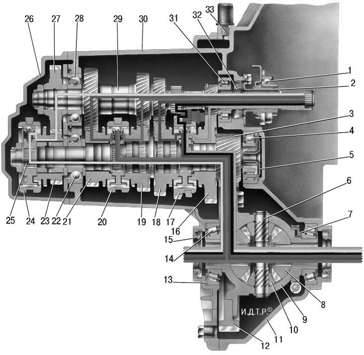
Pic. 6.4. Transmission: 1 - clutch release bearing; 2 - guide sleeve of the clutch release bearing; 3 – a gear wheel leading the main transfer; 4 - roller bearing of the secondary shaft; 5 - oil collector; 6 - the axis of the satellites; 7 – a driving gear wheel of a drive of a speedometer; 8 – half shaft gear; 9 - differential box; 10 - satellite; 11 - clutch housing; 12 - driven gear of the main gear; 13 - adjusting ring; 14 - roller tapered differential bearing; 15 - axle shaft seal; 16 - driven gear of the 1st gear of the secondary shaft; 17 - synchronizer of I and II gears; 18 - driven gear of the second gear of the secondary shaft; 19 - driven gear of the third gear of the secondary shaft; 20 - synchronizer III and IV gears; 21 - driven gear of the fourth gear of the secondary shaft; 22 - ball bearing of the secondary shaft; 23 - driven gear of the V transmission of the secondary shaft; 24 - synchronizer V transmission; 25 - secondary shaft; 26 – a back cover of a case of a transmission; 27 - drive gear V transmission; 28 - ball bearing input shaft; 29 - input shaft; 30 - gearbox housing; 31 - roller bearing input shaft; 32 – an epiploon of a primary shaft; 33 - breather
Gearshift drive consists of lever 15 (pic. 6.5) gear shifting, ball joint 17, thrust 14, gear selection rod 5, gear selection and shifting mechanisms.
In order to prevent spontaneous disengagement of gears due to axial movement of the power unit on its supports when the vehicle is moving, a reactive thrust 18 is introduced into the gearbox control drive, one end of which is connected to the power unit, and a holder 16 of the ball bearing of the gear lever 15 is attached to the other end.
At the inner end of the rod 5, a lever 1 is fixed, which acts on the three-arm lever 2 of the gear selection mechanism. This mechanism is made as a separate unit and is attached to the plane of the clutch housing.
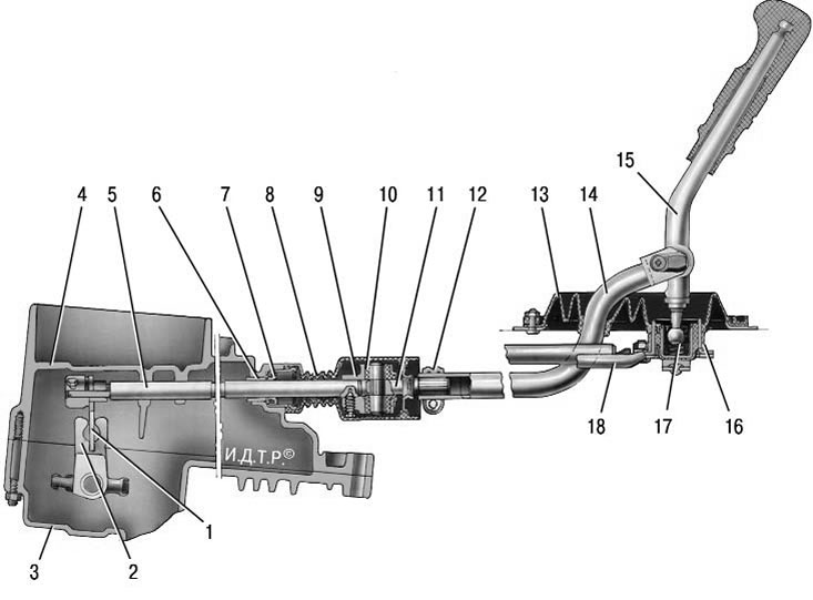
Pic. 6.5. Gear shift drive: 1 – gear selection rod lever; 2 - gear selection lever; 3 - gearbox housing; 4 - clutch housing; 5 – a stock of a choice of transfers; 6 - stem bushing; 7 - stem gland; 8 - protective cover; 9 – hinge body; 10 - hinge bushing; 11 – hinge tip; 12 - collar; 13 – a protective cover of draft; 14 – draft of a drive of management of a transmission; 15 - gearshift lever; 16 - holder of the ball bearing; 17 - ball bearing of the gear lever; 18 - jet thrust
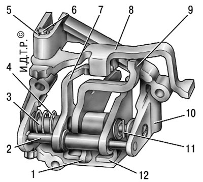
Pic. 6.6. Gear selection mechanism: 1 - gear selection lever (forward); 2 - guide axis of the locking brackets; 3 – an axis of the lever of a choice of transfers; 4, 11 - springs; 5 - retaining ring; 6 - axis of the reverse fork; 7, 12 - blocking brackets; 8 – a fork of inclusion of a backing; 9 - gear selection lever (reversing); 10 – the case of the mechanism of a choice of transfers
In building 10 (pic. 6.6) gear selector mounted two axles. Axle 3 is equipped with a three-arm gear selection lever, two locking brackets 7 and 12. The other axle 2 passes through the holes of the locking brackets, fixing them from turning. The lever arm 1 of the gear selection is used to engage forward gears, the lever arm 9 is used to engage reverse gear, and the lever of the gear selection rod acts on the third arm. A fork 8 for reversing is installed on the axis 6.
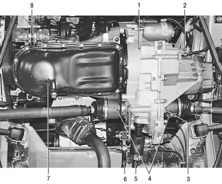
Pic. 6.7. The location of the gearbox on the car (bottom view): 1 - gearbox; 2 - reverse light switch; 3 - plug holes for draining oil from the gearbox; 4 - internal hinges of equal angular velocities; 5 – draft of a drive of a gear change; 6 - reactive thrust of the gear change drive; 7 - engine; 8 - right support of the power unit
The location of the gearbox on the car is shown in fig. 6.7.
Oil is poured into the gearbox, the level of which should be between the control marks of the oil level indicator.
Note. When refueling the box, try to pour a little more oil into it (about 100 ml), than recommended by the manufacturer. Such a measure will provide better operating conditions for the 5th gear bearing, located high in the crankcase and lubricated only by splashing.