
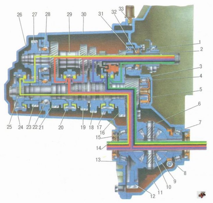
Input shaft 29 (pic. 5.2) The gearbox is made in the form of a block of driving gears, which are in constant engagement with the driven gears of all forward gears. The secondary shaft 25 is hollow, with a removable drive gear 3 of the main gear. On the secondary shaft of the gearbox are driven gears 16, 18, 19, 21, 23 and synchronizers 17, 20, 24 forward gears. The front bearings 4, 31 of the shaft are roller, the rear 22, 28 are ball bearings. An oil sump 5 is located under the front bearing of the output shaft of the gearbox, directing the oil flow into the output shaft and further under the driven gears.
Double satellite differential. The preload in the differential bearings is adjusted by selecting the thickness of the ring 13. The driven gear 12 of the final drive is attached to the flange of the differential box. On one of the trunnions of the differential box, a master ring 7 of the magnetoelectric speed sensor is installed.
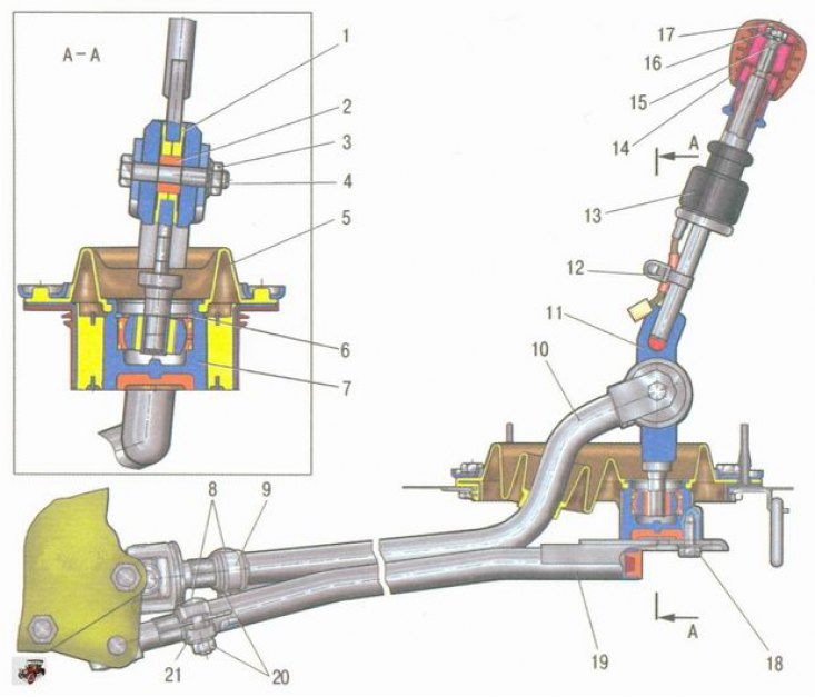
The gearbox control drive consists of a lever 11 (pic. 5.3) gear change, ball joint, thrust 10 and gear selection mechanism (installed in the gearbox housing). In order to exclude spontaneous disengagement of gears due to axial movement of the power unit on its supports while the Lada Kalina car is moving, a jet thrust 19 is introduced into the gearbox control drive, one end of which is connected to the power unit, and a body 7 of the ball bearing of the lever is attached to the other end gear shifting.
The reverse gear lock is controlled by a solenoid mounted on the gearbox housing, which, in turn, is controlled by a switch 13 mounted on the gear lever 11.
On a Lada Kalina car, the gear selection mechanism is made as a separate unit and is attached to the plane of the clutch housing inside the gearbox.
In building 9 (pic. 5.4) gear selection mechanism fixed two axles. A three-arm gear selection lever 2 and two locking brackets 7 and 11 are installed on axle 3. Another axle 1 passes through the holes of the locking brackets, fixing them from turning. Shoulder b three-arm lever 2 is used to engage forward gears, the lever A - to turn on the reverse gear, and the lever of the gear selection rod connected through the cardan joint with the rod 10 acts on the third arm (see fig. 5.3) gearbox control drive. On axis 6 (see fig. 5.4) fork 8 for reverse gear is installed. The gearbox is filled with gear oil, the level of which should be between the check marks on the oil level indicator.
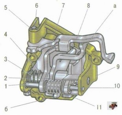
Pic. 5.4. Gear selection mechanism: 1 - guide axis of the locking brackets; 2 - three-arm lever; 3 - axis of the gear selection lever; 4, 10 - spring; 5 - retaining ring; 6 - axis of the reverse fork; 7, 11 - locking brackets; 8 - reverse gear engagement fork; 9 - housing of the gear selection mechanism; a - a shoulder of a three-arm lever for engaging reverse gear; b - shoulder of the three-arm lever for selecting forward gears
Pic. 5.3. Gear shift drive: 1 - damper sleeve; 2 - remote bushing; 3, 16, 20 - nuts; 4, 8, 18 - bolts; 5 - protective cover; 6 - retaining ring; 7 - body of the ball bearing; 9, 21 - clamps; 10 - thrust of the gearbox control drive; 11 - gear lever; 12 - clamp for fastening the wiring harness; 13 - switch of the solenoid for controlling the reverse gear lock; 14 - gear lever handle; 15 - washer; 17 - cover of the gear lever handle; 19 - jet thrust
Pic. 5.2. Transmission: 1 - clutch release bearing; 2 - guide sleeve of the clutch release bearing; 3 - main gear drive gear; 4 - roller bearing of the secondary shaft; 5 - oil collector; 6 - axis of the satellites; 7 - setting ring of the speed sensor; 8 - axle gear; 9 - differential box; 10 - satellite; 11 - clutch housing; 12 - driven gear of the main gear; 13 - adjusting ring; 14 - differential tapered roller bearing; 15 - axle shaft seal; 16 - driven gear of the 1st gear of the secondary shaft; 17 - synchronizer of I and III gears; 18 - driven gear of the second gear of the secondary shaft; 19 - driven gear of the third gear of the secondary shaft; 20 - synchronizer of III and IV gears; 21 - driven gear of the IV gear of the secondary shaft; 22 - ball bearing of the secondary shaft; 23 - driven gear of the V transmission of the secondary shaft; 24 - synchronizer V transmission; 25 - secondary shaft; 26 - rear cover of the gearbox housing; 27 - drive gear V gear; 28 - ball bearing of the input shaft; 29 - input shaft; 30 - gearbox housing; 31 - roller bearing of the input shaft; 32 - input shaft seal; 33 - breather