



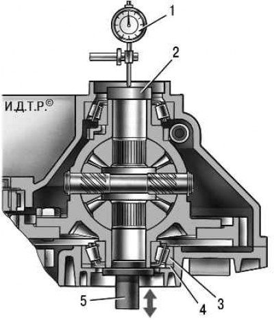
Figure 6.10. Scheme for selecting the thickness of the differential bearing adjusting ring: 1 – indicator; 2 – support plate; 3 – differential bearing; 4 – mounting ring; 5 – mandrel
The preliminary tension of the differential bearings should be 0.15–0.35 mm. The tension is provided by selecting the thickness of the adjusting ring from those supplied as spare parts. The adjusting ring is installed in the socket of the gearbox housing under the outer ring of the differential bearing. The diagram for selecting the thickness of the differential bearing adjusting ring is shown in the figure 6.10.
1. Press the outer race of the differential bearing out of the gearbox housing if this has not been done previously (see "Differential repair").
2. Insert a 1.25 mm thick locating ring into the socket in the gearbox housing under the differential bearing and press the outer race of the differential bearing into the socket in the gearbox housing using a suitable drift. Press the bearing ring into the clutch housing if it was pressed out.
The original was published on the portal (LADAMAN)
3. Install the differential into the gearbox housing.
4. Install the clutch housing onto the gearbox housing and tighten three equally spaced housing mounting bolts to the appropriate torque. Rotate the differential a few turns to allow the bearings to self-align.
5. Install a support plate of the appropriate diameter on the end of the differential flange on the clutch housing side.
6. Install the indicator on the stand. Place the indicator leg on the support plate with a pre-tension of 1 mm.
7. Applying force from below, move the differential upward until it stops. In this case, the differential cannot be turned around the axis.
8. Measure the differential axial movement using the indicator readings. Calculate the required thickness of the differential bearing adjusting ring using the formula
T = S + C + Y, Where
T — required thickness of the adjusting ring, mm;
S — measured axial displacement of the differential, mm;
C — differential bearing preload equal to 0.25 mm;
Y — the thickness of the mounting ring is 1.25 mm.
Select an adjusting ring of the calculated thickness (T±0.1) mm from those supplied as spare parts.
Example of calculating the thickness of the adjustment ring
The axial clearance S when reading the indicator is 0.95 mm. We substitute this value, the bearing preload value (C = 0.25 mm) and the thickness of the mounting ring (Y = 1.25 mm) into the formula. We get T = 0.95 + 0.25 + 1.25 = 2.45 (mm).
The resulting thickness T of the adjustment ring should be (2.45±0.1) mm.
Install the selected adjusting ring into the gearbox housing socket and press in the outer ring of the differential bearing.