



You will need two 13 mm keys.
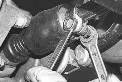
1. From underneath the vehicle, loosen and unscrew the nut on the clamp bolt on the gearbox control rod by 3–5 turns.
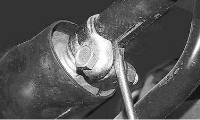
2. Use a screwdriver to slightly widen the groove in the clamp and the groove at the end of the rod to ensure free movement of the rod relative to the gear selection rod, and set the rod to the neutral position.
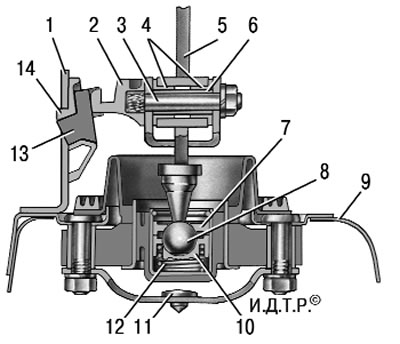
Figure 6.11. Gear shift lever position adjustment diagram: 1 – reverse gear lock bracket; 2 – axle stop; 3 – gear shift lever axis; 4 – axle bushings; 5 – gear shift lever; 6 – spacer sleeve; 7 – spherical washer of ball joint; 8 – spherical pin of the gear shift lever; 9 – body floor; 10 – ball joint; 11 – buffer; 12 – spring; 13 – template 67.7834.9527; 14 – bracket cover
3. In the car, remove the gearshift lever cover from the handle, lower the cover down the lever and install the lever so that its bottom (straight) the end is positioned approximately vertically. If you have template 67.7834.9527, set the gear shift lever as follows: with the lever boot removed, install the template in the window of the lining 14 (figure 6.11) reverse gear lock bracket. Insert stop 2 of lever 5 axis into template groove 13 and press it against the template in the transverse direction without causing elastic deformation of bracket 1. Fix lever 5 in this position.
[The original was published on the portal: www.LadaMan.ru]
4. From below the car with light hand movements (to avoid moving the gear selector levers) select the axial play of the rod in the rearward direction and its angular play in the counterclockwise direction.
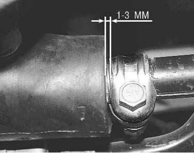
5. Tighten the clamp tie bolt nut, positioning the clamp at a distance of 1–3 mm from the end of the rod.