
Removing
Place the vehicle on a two-post lift, apply the parking brake and turn off the ignition.
Remove the engine crankcase protection.
Unscrew the two nuts 1, Figure 10-1, securing the expansion tank.
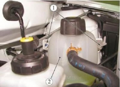
Figure 10-1 - Detaching the expansion tank: 1 - expansion tank nut; 2 - expansion tank
Remove expansion tank 2 and lay aside without disconnecting hoses.
Disconnect connector 1, Figure 10-2, brake fluid level sensor.
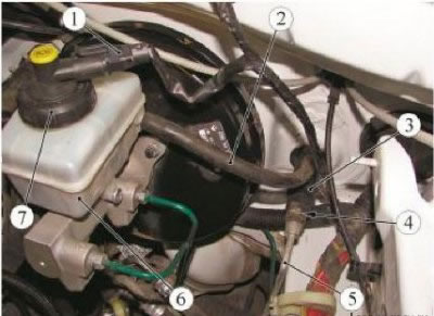
Figure 10-2 - Removing the hydraulic clutch pipeline: 1 - brake fluid level sensor connector; 2 - supply pipeline of the main cylinder of the clutch drive; 3 - the main cylinder of the clutch drive; 4 - latch; 5 - pipeline connecting the main and working cylinders of the clutch drive; 6 - a reservoir of a hydraulic drive of brakes; 7 - stopper of a reservoir of a hydraulic drive of brakes
Remove the cap 7 of the hydraulic brake reservoir.
Remove the brake fluid from the reservoir 6 of the hydraulic brake drive with a syringe so that its level is below the fluid supply hole to the clutch master cylinder on the reservoir.
Place a rag under the opening of the hydraulic brake reservoir.
Disconnect pipe 2 for clutch master cylinder from hydraulic brake reservoir.
Insert plugs into the openings of the pipeline and tank (technological plugs).
Place a rag under the clutch slave cylinder.
Remove plug 1, Figure 10-3, from the bleeder port.
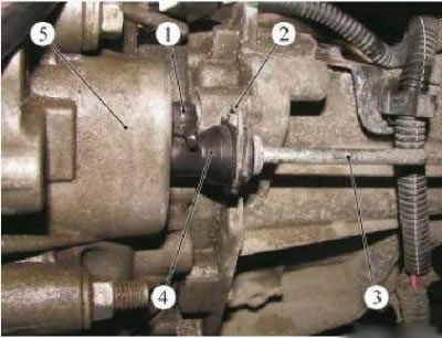
Figure 10-3 - Removing brake fluid from the clutch hydraulic system: 1 - a plug of the union for removal of air; 2 - latch; 3 - pipeline connecting the main and working cylinders of the clutch drive; 4 - working cylinder of the clutch drive; 5 - gearbox
Connect a transparent hose to the bleeder fitting, dropping the other end into an empty vessel below the bleeder hole.
Press the latch 2 and pull out the pipeline 3 by one click to open the air vent hole.
Depress the clutch pedal by hand to remove fluid from the clutch master cylinder and piping.
Place a rag under the clutch master cylinder.
Raise the latch 4, Figure 10-1, fastening the pipeline 5 connecting the master and slave cylinders of the clutch actuator on the master cylinder.
Disconnect line 5 from clutch master cylinder.
Insert plugs into the holes on the pipeline and clutch master cylinder (technological plugs).
Press holder 2, Figure 10-3, of the clutch slave cylinder.
Disconnect the pipeline 3 from the working cylinder 4 of the clutch drive and install the plugs in the openings of the working cylinder and the pipeline.
Disconnect the pipeline connecting the master and slave cylinders from the mounting brackets on the body and gearbox.
Remove pipe 3 connecting the master and slave cylinders of the clutch hydraulic drive.
Installation
Check the condition of the sealing rings on the pipeline connecting the main and working cylinders of the clutch hydraulic drive, replace if necessary.
Remove the technological plugs from the holes of the hydraulic drive elements.
Install the pipeline connecting the master and slave cylinders of the clutch hydraulic actuator.
Fix the pipeline connecting the master and slave cylinders of the hydraulic clutch in the mounting brackets on the gearbox and on the body.
Connect pipe 5, Figure 10-2, to clutch master cylinder 3.
Install pipe retainer 4 between the master and slave cylinders on the clutch master cylinder.
Connect the pipeline 3, Figure 10-3, connecting the clutch master and slave cylinders to the clutch slave cylinder 4.
Install the expansion tank 2, Figure 10-1, and tighten the nuts 1 of the expansion tank with a torque of 8 Nm (0.8 kgf·m) (wrench 10, interchangeable head 10, extension, torque wrench).
Pour brake fluid into the reservoir and top up the level. The brake fluid level must be between the marks "MAX" And "MIN" (brake fluid according to the current "Codifier of the main and auxiliary materials used in the maintenance and repair of LADA vehicles" K 3100.25100.00018).
Bleed the air from the hydraulic clutch.
Check clutch operation.
Install crankcase protection