
Removing
Place the vehicle on a two-post lift, brake with the parking brake, turn off the ignition, open the hood and disconnect the wire terminal "masses" from the battery.
Remove the engine crankcase protection.
Loosen two nuts 1, Figure 9-1, fixing the expansion tank (wrench).
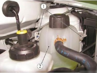
Figure 9-1 - Removing the expansion tank: 1 - expansion tank nut; 2 - expansion tank
Remove expansion tank 2 and lay aside without disconnecting hoses. Disconnect connector 1, Figure 9-2, brake fluid level sensor.
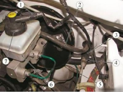
Figure 9-2 - Removing the clutch master cylinder: 1 - brake fluid level sensor connector; 2 - supply pipeline of the main cylinder of the clutch drive; 3 - the main cylinder of the clutch drive; 4 - latch; 5 - pipeline connecting the main and working cylinders of the clutch drive; 6 - a reservoir of a hydraulic drive of brakes; 7 - stopper of a reservoir of a hydraulic drive of brakes
Remove the cap 7 of the hydraulic brake reservoir.
Remove the brake fluid from the reservoir 6 of the hydraulic brake drive with a syringe so that its level is below the fluid supply hole to the clutch master cylinder on the reservoir.
Place a rag under the opening of the hydraulic brake reservoir.
Disconnect pipe 2 for clutch master cylinder from hydraulic brake reservoir.
Insert plugs into the openings of the pipeline and tank (technological plugs).
Place a rag under the clutch slave cylinder.
Remove plug 1, Figure 9-3, from the bleeder port.
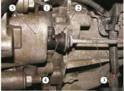
Figure 9-3 - Removing brake fluid from the clutch hydraulic system: 1 - a plug of the union for removal of air; 2 - latch; 3 - pipeline connecting the main and working cylinders of the clutch drive; 4 - working cylinder of the clutch drive; 5 - gearbox
Connect a transparent hose to the bleeder fitting, dropping the other end into an empty vessel below the bleeder hole.
Press the latch 2 and pull out the pipeline 3 by one click to open the air vent hole.
Depress the clutch pedal by hand to remove fluid from the master cylinder and pipeline.
Place a rag under the clutch master cylinder.
Raise the latch 4, Figure 9-1, fastening the pipeline 5 connecting the master and slave cylinders of the clutch actuator on the master cylinder.
Disconnect line 5 from clutch master cylinder.
Insert plugs into the holes on the pipeline and clutch master cylinder (technological plugs).
Remove from the fastening brackets and take aside the pipeline 5.
Disconnect pusher ball head 1, Figure 9-4, clutch master cylinder from clutch pedal 2 in passenger compartment.
Remove the clutch master cylinder from the bulkhead by turning it a quarter of a turn clockwise in the engine compartment using the tool, Figure 9-5 (device Emb. 1596 or Emb. 1797 to remove the clutch master cylinder, crank).
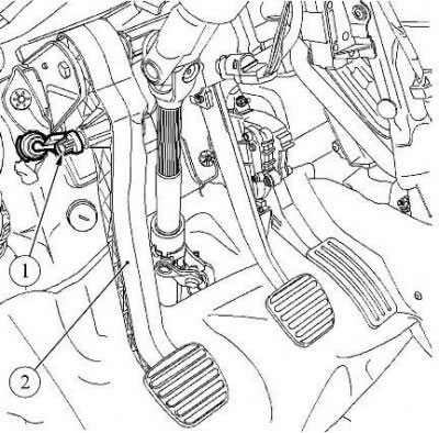
Figure 9-4 - Disconnecting the clutch master cylinder from the clutch pedal: 1 - pusher of the clutch master cylinder; 2 - clutch pedal
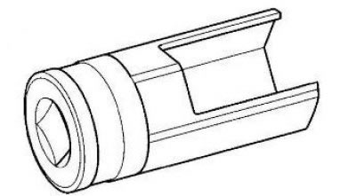
Figure 9-5 - Attachment Emb. 1596 to remove the clutch master cylinder
Installation
Check the condition of the O-ring on the pipeline 5, Figure 9-2, replace if necessary.
Install the clutch master cylinder 3 by turning it a quarter of a turn counterclockwise using the tool, Figure 9-5 (device Emb. 1596 or Emb. 1797 to remove the clutch master cylinder, crank).
Attention! When installing the clutch master cylinder, do not use the nipple as a stop.
Install the pushrod ball head 1, Figure 9-4, of the clutch master cylinder onto the clutch pedal 2 in the passenger compartment.
Remove the plugs from the openings of the pipeline and the clutch master cylinder.
Install pipeline 5 connecting the master and slave cylinders of the clutch actuator to the master cylinder.
Press the latch 4 of the clutch master cylinder.
Secure hydraulic clutch line with body clips.
Lubricate the end of supply line 2 of the clutch master cylinder with brake fluid.
Connect the supply line of the clutch master cylinder to the reservoir 6 of the hydraulic brake drive.
Install the expansion tank 2, Figure 9-1, and tighten the nuts 1 of the expansion tank with a torque of 8 Nm (0.8 kgf·m) (wrench 10, interchangeable head 10, extension, torque wrench).
Pour brake fluid into the reservoir and top up the level. The brake fluid level must be between the marks "MAX" And "MIN" (brake fluid according to the current "Codifier of the main and auxiliary materials used in the maintenance and repair of LADA vehicles" K 3100.25100.00018).
Bleed the air from the hydraulic clutch.
Check clutch operation.
Install the engine crankcase protection.