



Removal
Place the vehicle on a work stand, apply the parking brake, turn off the ignition and disconnect the ground wire terminal from the battery (spanner 10).
Remove the air filter with the intake pipe hose and the air supply pipe assembly in accordance with the requirements of Section 3 of this TI.
Remove the engine mudguard in accordance with the requirements of TI 3100.25100.20594.
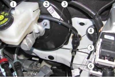
Figure 11-1 - Removing the clutch hydraulic drive: 1 - cork; 2 - hydraulic brake reservoir; 3 - tube; 4 - clutch master cylinder; 5 - retainer bracket; 6 - clutch hydraulic tube
Unscrew plug 1, Figure 11-1, of the hydraulic brake reservoir and pump out the brake fluid to a level below the nipple of tube 3. Screw plug 1 back into place (brush pump, process tank).
Disconnect tube 3 from the nipple of reservoir 2 of hydraulic brakes and drain the remaining brake fluid from the tube (technological capacity).
Disconnect tube 3 from clutch master cylinder 4 and install technological plugs on the fittings and in the tube holes (technological plugs).
For vehicles with JH3 gearbox and H4M engine
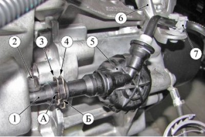
Figure 11-2 - Removing the clutch hydraulic drive: 1 - clutch working cylinder; 2 - protective cap for air bleed nipple; 3, 4 - retainer; 5 - clutch hydraulic tube with damper assembly; 6 - left engine support bracket; 7 - clutch hydraulic tube mounting bracket; A, B - rib, limiter of the latch stroke
Raise the retainer 3, Figure 11-2, up until the retainer's antennae rest against the ribs "A", remove the clutch hydraulic drive tube 5 from the working cylinder 1 and install technological plugs on the tube and in the opening of the clutch working cylinder. When performing this operation, the lock 4 must remain in the recessed position; the lock 4 is used when performing the "air removal" procedure (technological plugs).
Remove the clutch hydraulic drive tube 5 from the mounting bracket 7.
For vehicles with JR5 gearbox and 21129 engine
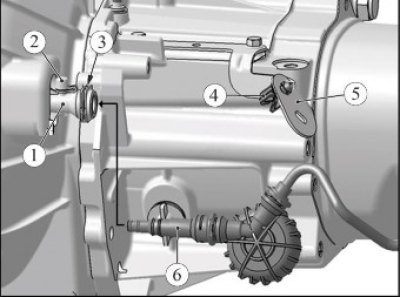
Figure 11-3 - Clutch hydraulic line: 1 - clutch working cylinder; 2 - protective cap for air bleed nipple; 3 - retainer; 4 - clutch hydraulic tube mounting bracket; 5 - bracket; 6 - clutch hydraulic tube with damper assembly
Remove tube 6, Figure 11-3, of the clutch hydraulic drive from the mounting bracket 4.
Press the lock 3 and remove the tube 6 of the clutch hydraulic drive from the working cylinder 1. Install technological plugs on the tube and in the opening of the clutch working cylinder. Remove the tube from the work area (technological plugs).
For all cars
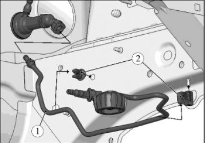
Figure 11-4 - Removing the clutch hydraulic drive: 1 - clutch hydraulic tube; 2 - mounting bracket
Remove the tube 1, Figure 11-4, of the clutch hydraulic drive from the mounting brackets 2 and remove it from the vehicle.
Insert the tip of a flat-head screwdriver into the gap between rod 1, Figure 10-1, of the clutch master cylinder and the clutch pedal 3 and, overcoming the resistance, disconnect the rod from the clutch pedal (flat head screwdriver).
Turn the clutch master cylinder 1/8 turn clockwise and remove it from the hole in the front shield. Work must be carried out from the engine compartment. The clutch master cylinder is attached to the front shield using a bayonet lock (spanner 24).
Remove the gearbox in accordance with the requirements of Section 3 of this TI.
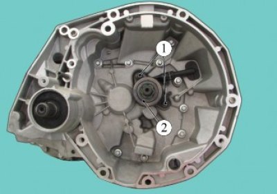
Figure 11-5 - Removing the clutch release sleeve: 1 - mounting bolts; 2 - clutch release sleeve assembled with clutch slave cylinder
Install the gearbox on a workbench, unscrew the two bolts 1, Figure 11-5, and remove the clutch release coupling 2 together with the clutch slave cylinder (replacement head 10, extension, ratchet).
Installation
Install the clutch release coupling 2, Figure 11-5, together with the clutch slave cylinder into the gearbox and tighten the two mounting bolts 1. Bolt tightening torque 18.24 Nm (1.8...2.4 kgf·m) (replaceable head 10, extension, ratchet, torque wrench).
Attention. Before installing the clutch release sleeve, it is necessary to pre-fill the clutch slave cylinder with brake fluid (technological syringe, brake fluid according to the current "Codifier of the main and auxiliary materials used in the maintenance and repair of LADA vehicles" K 3100.25100.00018).
Install the gearbox in accordance with the requirements of Section 3 of this TI.
Remove the technological plugs from the clutch hydraulic drive pipe and the clutch slave cylinder.
Check the condition of the sealing rings on the fittings of tube 1, Figure 11-4, of the clutch hydraulic drive and replace if necessary.
Lubricate the sealing rings on the fittings of the clutch hydraulic tube with brake fluid and install tube 1 in brackets 2 and in bracket 7, Figure 11-2, of the fastening.
For vehicles with JH3 gearbox and H4M engine
Connect the pipe 5, Figure 11-2, of the clutch hydraulic drive to the clutch slave cylinder 1 and make sure that it is securely fixed (locks 3 and 4 must be in the extreme lower position).
Fasten tube 5 to bracket 7.
For vehicles with JR5 gearbox and 21129 engine
Connect pipe 6, Figure 11-3, of the clutch hydraulic drive to the clutch slave cylinder 1 and make sure that it is securely fastened.
Fasten tube 6 to bracket 4.
For all cars
Install the clutch master cylinder into the hole in the front shield and turn it 1/8 turn counterclockwise. Work must be carried out from the engine compartment. The clutch master cylinder is attached to the front shield using a bayonet lock (spanner 24).
Apply grease to the spherical pin of the clutch pedal 3, Figure 10-1, and attach the rod 1 of the clutch master cylinder to the clutch pedal (AZMOL LSC-15 grease according to the current "Codifier of the main and auxiliary materials used in the maintenance and repair of LADA vehicles" K 3100.25100.00018, consumption rate 1 g).
Connect pipe 6, Figure 11-1, of the clutch hydraulic drive to the clutch master cylinder 4 and make sure that it is securely fastened.
Connect tube 3 to the nipple of the clutch master cylinder 4 and to the nipple of the hydraulic brake reservoir 2.
Unscrew plug 1 of the hydraulic brake reservoir, fill with brake fluid and remove air from the clutch hydraulic drive in accordance with the requirements of Section 12 of this TI.
Install the air filter with the intake pipe hose and the air supply pipe assembly in accordance with the requirements of Section 3 of this TI.
Install the engine mudguard in accordance with the requirements of TI 3100.25100.20594.
Connect the ground wire terminal to the battery and tighten the mounting nut. Tightening torque of the nut 4...6 Nm (0.4...0.6 kgf·m) (replaceable head 10, torque wrench).
Present the vehicle to the Quality Control Department. The Quality Control Department will check the vehicle for compliance with the requirements of TU 017200-254-00232934, paragraphs 1.19.15, 1.19.16.