



Removal
Place the vehicle on a two-post lift, apply the parking brake, turn off the ignition, open the hood and disconnect the ground wire from the battery (two-post lift type P3.2G with a lifting capacity of 3.2 t, spanner 10).
Loosen the front wheel mounting bolts (replacement head 17, extension and ratchet).
Remove the caps and unscrew the nuts securing the front wheel hubs (replacement head 30, ratchet).
Loosen the bolts and remove the front wheels (replacement head 17, extension and ratchet). Remove the engine mudguard in accordance with the requirements of TI 3100.25100.20594.
Drain the oil from the gearbox in accordance with the requirements of Section 3 of this TI.
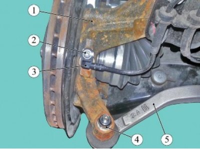
Figure 13-1 - Disconnecting: 1 - steering knuckle; 2 - screw; 3 - front wheel speed sensor; 4 - nut; 5 - steering rod end
Loosen screw 2, figure 13-1, of the fastening and remove speed sensor 3 from steering knuckle 3 (torx T30 Angle Key).
Loosen nut 4 securing outer end 5 of steering rod to steering knuckle 1, holding the ball pin from turning if necessary, and disconnect the steering rod end from the steering knuckle (16 ring spanner, T30 Torx angle spanner, tie rod end puller).
Loosen bolt 4, Figure 13-2, of the fastening and remove bracket 5 from the work area (replacement head 10, ratchet).
Unscrew two nuts 6, remove bolts 2 and disconnect steering knuckle 1 from strut 3 of the front suspension (ring spanner 18, replaceable head 18, ratchet).
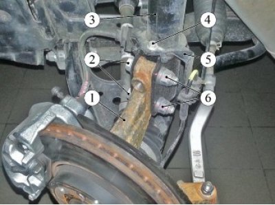
Figure 13-2 - Disconnecting: 1 - steering knuckle; 2 - bolt; 3 - telescopic strut of the front suspension; 4 - bolt; 5 - bracket; 6 - nut
Attention. Removal, installation and transportation of front wheel drives must be performed in such a way as to prevent self-disassembly of the inner drive joint. The internal hinge is made according to the "Tripod" scheme. The axial movement of the hinge in the housing is not structurally limited. The hinge is held in the housing only by the elasticity of the mudguard and, if handled carelessly, can slip out of the housing and tear the mudguard. It is not allowed to move the drive by holding it only by the inner hinge housing.
Tilt the steering knuckle and remove the splined portion of the front wheel drive from the front wheel hub and remove the drive.
Knock out and remove the front wheel drive from the differential axle gear. When removing both the right and left wheel drives, install transport plugs in the gearbox in their place (transport plug 21080-1700030-00, mounting blade).
Secure the steering knuckle to the front suspension strut with a bolt.
Installation
Check the condition of the front wheel drive oil seals and replace them if necessary in accordance with the requirements of Section 3 of this TI.
(Original posted on the website: www.Ladaman.ru)
Check that the installed drive matches the vehicle configuration.
When installing a drive previously removed from a vehicle, remove the old one and install a new retaining ring on the tip of the inner joint of the front wheel drive. Reuse of retaining rings is not permitted (flat head screwdriver).
Remove the transport plug from the gearbox differential. Insert the splined part of the inner joint of one of the drives into the axle shaft seal, turn the drive shaft and, aligning the joint splines with the axle shaft gear recesses, install the drive into the gearbox.
Make sure that the drive is fixed in the gear using your hands, applying a load to the inner joint towards the steering knuckle.
Insert the splined part of the outer drive joint into the wheel hub and screw on, without tightening, a new hub mounting nut (replacement head 30, ratchet).
Attach steering knuckle 1, Figure 13-2, to strut 3 of the front suspension, insert bolts 2 and tighten fastening nuts 6. Tightening torque of nuts 90...120 Nm (9.0...12.0 kgf·m) (ring spanner 18, replaceable head 18, ratchet, torque wrench).
Attach the outer end 5, Figure 13-1, of the steering rod to the steering knuckle 1 and tighten the fastening nut 4, holding the ball pin from turning if necessary. Nut tightening torque 32...42 Nm (3.2...4.2 kgf·m) (ring spanner 16, Torx T30 angle spanner, replaceable ring socket 16, torque wrench).
Install bracket 5 on pillar 3, Figure 13-2, of the front suspension and tighten mounting bolt 4. Bolt tightening torque 7...9 Nm (0.7...0.9 kgf·m) (replaceable head 10, ratchet, torque wrench).
Install sensor 3 in place, Figure 13-1, tighten the screw 2 for fastening. Bolt tightening torque 7...9 Nm (0.7...0.9 kgf·m) (torx T30 replacement bit, extension, ratchet, torque wrench).
Install the front wheels in accordance with the requirements of TI 3100.25100.20594.
Finally tighten the front wheel hub mounting nut and install the wheel center cap in place. Nut tightening torque 238...322 N·m (23.8...32.2 kgf·m) (replaceable head 30, ratchet, torque wrench).
Fill the gearbox with oil in accordance with the requirements of Section 3 of this TI.
Install the engine mudguard in accordance with the requirements of TI 3100.25100.20594.
Connect the ground wire terminal to the battery and tighten the mounting nut. Tightening torque of the nut 4...6 Nm (0.4...0.6 kgf·m) (replaceable head 10, torque wrench).
Present the vehicle to the Quality Control Department. The Quality Control Department will check the vehicle for compliance with the requirements of TU 017200-254-00232934, paragraphs 1.19.8, 1.19.13, 1.19.18.