



Removal
Place the vehicle on a two-post lift, apply the parking brake, turn off the ignition, open the hood and disconnect the ground wire from the battery (two-post lift type P3.2G with a lifting capacity of 3.2 t, spanner 10).
Remove the gearbox in accordance with the requirements of Section 3 of this TI.
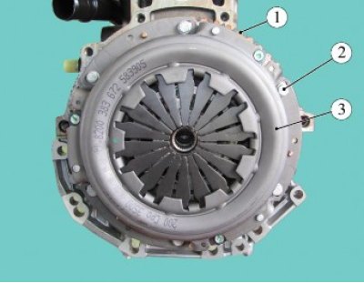
Figure 8-1 - Removing the clutch: 1 - flywheel; 2 - mounting bolt; 3 - clutch assembly
Install the flywheel lock on the engine cylinder block, unscrew the six bolts 2, Figure 8-1, securing the clutch pressure plate to the flywheel 1 and remove the clutch 3 as an assembly (for engines 21129 and 21179 - replaceable head 8, ratchet, flywheel lock 67.7820-9526; for the H4M engine - replaceable head 12, ratchet, flywheel lock 67.7820-9708).
Checking the pressure and driven clutch discs
Inspect the driven clutch disc. If there are cracks, dents, breaks in the damper springs and cracks or delamination of the friction linings, the disc must be replaced.
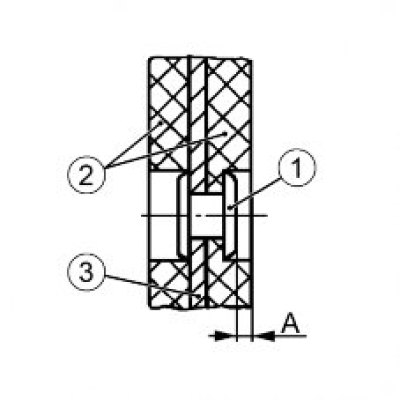
Figure 8-2 - Determining the amount of wear on the clutch driven disc linings: 1 - rivet; 2 - friction lining; 3 - slave disk; A - distance between the end of the rivet and the working surface of the pad
Measure the distance "A", Figure 8-2, between the end of the rivet 1 and the working surface of the lining 2. If the value A = 0.2 mm or less, the driven disk must be replaced (caliper TTTTs 1-125-01).
Inspect the clutch pressure plate. There should be no scratches or traces of tarnish on the surface of the disc that contacts the driven clutch disc. If there are cracks or breakages in the petals of the pressure spring, the disc must be replaced.
Installation
Check that the installed clutch matches the vehicle configuration.
Clean and wash the splines in the clutch driven disk hub and on the gearbox input shaft (white spirit, consumption rate 10 g).
Install clutch 3, Figure 8-1, as an assembly on flywheel pins 1 and tighten, without tightening, mounting bolts 2 (replaceable head 8 or 12, ratchet).
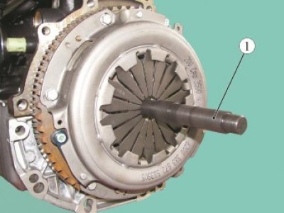
Figure 8-3 - Centering the Clutch Driven Disc: 1 - mandrel for centering the driven clutch disc
Install mandrel 1, Figure 8-3, into the driven disk hub and center the driven clutch disk relative to the engine flywheel (for engines 21129 and 21179 - mandrel A.70081; for the H4M engine - the mandrel is supplied in the spare parts kit with the clutch disc).
Install the flywheel retainer on the engine cylinder block and tighten the six bolts 2, Figure 8-1, securing the clutch pressure plate one by one in a crosswise pattern. Tightening torque of bolts 20...31 N·m (2.0...3.1 kgf·m) (for engines 21129 and 21179 - replaceable head 8, ratchet, torque wrench, flywheel lock 67.7820-9526; for the H4M engine - replaceable head 12, ratchet, torque wrench, flywheel lock 67.7820-9708).
Install the gearbox in accordance with the requirements of Section 3 of this TI.
Connect the ground wire terminal to the battery and tighten the mounting nut. Tightening torque of the nut 4...6 Nm (0.4...0.6 kgf·m) (replaceable head 10, torque wrench).
Present the car of the OTK. OTC check the vehicle for compliance with the requirements of TU 017200-254-00232934 clause 1.19.16.