



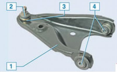
Front suspension arm: 1 – lever; 2 – ball joint boot; 3 – ball joint; 4 – suspension arm silent blocks (front and back)
Note: Part numbers for this unit can be found here here
Removal
Place the vehicle on a two-post lift, apply the parking brake and turn off the ignition.
Remove the front wheel.
Remove the front wing side mudguard (see here).
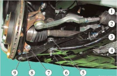
Figure 5-1 - Front Suspension Arm: 1 - front suspension subframe; 2 - nut of the rear bolt securing the lever to the subframe; 3 - front suspension arm; 4 - stabilizer bar for lateral stability; 5 - stabilizer bar for lateral stability; 6 - nut of the stabilizer bar mounting bolt; 7 - nut of the bolt securing the ball joint to the steering knuckle; 8 - steering knuckle; 9 - ball joint
Loosen nut 6, Fig. 5-1, of the bolt securing the anti-roll bar to arm 3 of the front suspension (torx T40 angle wrench, 13 mm replaceable head, ratchet wrench).
Remove the stabilizer bar components from the front suspension arm: the lower rubber-metal hinge, the mounting bolt, two rubber bushings, the upper rubber-metal hinge and the washer.
Loosen nut 7 of the bolt securing the ball joint of the front suspension arm to the steering knuckle and disconnect arm 3 from knuckle 8 (ring spanner 16, replaceable head 16, extension and ratchet).
Loosen and remove bolt 1, Figure 5-2, securing the front suspension subframe brace to the engine compartment side member (replaceable head 13, ratchet wrench).
Loosen nut 4 securing the front suspension subframe tie rod to the front suspension arm and remove rod 2 (ring spanner 18, replaceable head 18, ratchet spanner).
Loosen the nuts of the bolts securing the lower arm of the front suspension to the subframe, remove the bolts and remove arm 6 (ring spanner 18, replaceable head 18 extended, ratchet spanner).
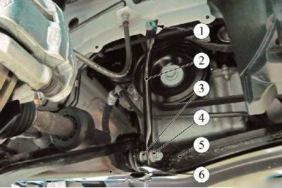
Figure 5-2 - Removing the front suspension subframe strut: 1 - bolt for fastening the subframe tie rod to the side member; 2 - front suspension subframe stretcher; 3 - nut of the front suspension arm mounting bolt; 4 - nut securing the subframe tie rod to the front suspension arm; 5 - front suspension subframe; 6 - front suspension arm
Attention!
- Reuse of front suspension arm mounting bolts and nuts is not permitted. Bolts and nuts must be replaced.
- Reuse of the ball joint mounting nut to the steering knuckle is not permitted. The nut must be replaced.
- Install the bolts securing the front suspension arm to the subframe with the heads facing the inner part of the arm.
- Install the bolt securing the ball joint of the lower arm of the front suspension to the steering knuckle with the head facing the front of the vehicle.
Install the lower arm of the front suspension on the subframe, install the mounting bolts and tighten the nuts without tightening them (ring spanner 18, replaceable head 18 extended, ratchet spanner).
Install the ball joint pin of the front suspension arm into the steering knuckle, install the mounting bolt and tighten the new nut. When assembling, the flange of the spacer washer must fit into the slot on the steering knuckle. Nut tightening torque 62 Nm (6.2 kgf·m) (ring spanner 16, replaceable head 16, ratchet spanner, torque wrench).
Installation
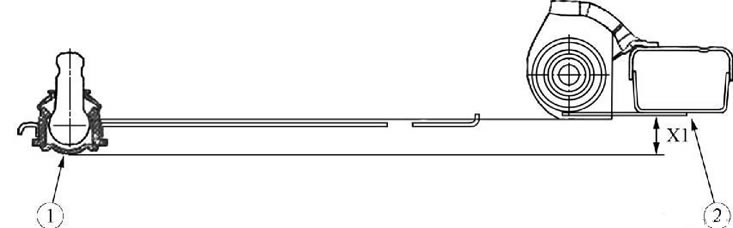
Figure 5-3 - Diagram of the location of the front suspension arm relative to the subframe when tightening the rubber-metal hinges: 1 - ball joint of the front suspension arm; 2 - front suspension subframe; X1 - size for installing the lever equal to 24 mm
Attention. To tighten the rubber-metal hinges of the front suspension arm in a non-submerged state, install the arm as shown in Figure 5-3. The vertical dimension from the bottom of the ball joint housing to the bottom of the subframe in the area of the hole in the center of the arm mount to the subframe should be equal to X1 = 24 mm.
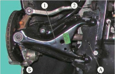
Figure 5-4 - Jack installation diagram when setting the XI dimension: 1 - front suspension arm; 2 - front suspension subframe; A - place for installing the jack under the subframe; B - place for installing the jack under the ball joint
The procedure for tightening the rubber-metal hinges of the front suspension arm:
- install a hydraulic jack under the subframe in the area of hole "A", Figure 5-4, in the center of the front suspension arm mount;
- adjust the height of the jack rod extension so that the distance between the jack heel and the bottom of the subframe corresponds to the dimension X1 = 24 mm, Figure 5-3;
- move the jack under the ball joint to point "B", Figure 5-4, and set the lever so that the ball joint housing lies on the heel of the jack rod;
- finally tighten the nuts of the front suspension arm bolts to the subframe. Tightening torque of nuts 105 Nm (10.5 kgf·m) (ring spanner 18, replaceable head 18 extended, torque wrench).
Install the anti-roll bar strut elements on the lever: washer, upper rubber-metal hinge, install two rubber bushings between the lever and the stabilizer, install the mounting bolt, lower rubber-metal hinge, tighten the package of strut elements with a clamp and tighten the nut. Nut tightening torque 14 Nm (1.4 kgf·m) (clamp Sus. 1413 and Sus. 1734, Torx T40 angle key, replaceable head 13, ratchet key, torque wrench).
Install the subframe brace in place and tighten the bolt securing the rod to the side member and the nut securing the rod to the front suspension arm. Tightening torques for bolts 62 N·m (6.2 kgf·m), nuts 62 N·m (6.2 kgf·m) (replaceable head 13, 18, ratchet wrench, torque wrench).
Install the front fender side mudguard.
Install the front wheel.
Check and adjust if necessary front wheel alignment angles.