



Removal
The work is carried out on a lift.
Using straps, secure the engine radiator to the front cross member of the engine compartment.
Remove the front wheels and engine sump guard.
Remove the front mudguards and mudguards.
Unscrew the three screws securing the bottom of the bumper to the front suspension subframe and remove the lower part of the bumper, releasing the subframe.
For vehicles with K7M engine, remove the catalytic converter.
Loosen and remove the bolts securing the subframe struts to the side members (13 mm head).
Loosen the nuts and remove the bolts securing the ball joints to the steering knuckles (16 mm spanner, 16 mm socket).
Disconnect the ball joints of the front suspension arms from the steering knuckles.
Loosen the bolt securing the low pressure line to the front suspension subframe (10 mm socket).
For vehicles with a K4M engine, remove the oxygen sensor wiring harness from the retainer on the steering gear heat shield, unscrew the steering gear heat shield mounting bolts and remove the shield (13 mm socket).
Loosen the bolts securing the steering gear to the subframe and attach the steering gear to the body (18 mm socket).
Unscrew and remove bolt 3, Figure 7-1, securing connecting bracket 4 to lower reaction rod 2 (18 mm head).
Slightly loosen bolt 5 securing the connecting bracket to gearbox housing 6 and turn bracket 4 away from reaction rod 2 (18 mm socket).
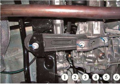
Figure 7-1 - Removing the connecting bracket from the reaction rod: 1 - front suspension subframe; 2 - lower jet thrust; 3 - mounting bolt; 4 - connecting bracket; 5 - mounting bolt; 6 - gearbox housing
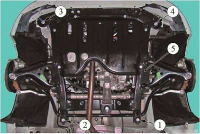
Figure 7-2 - Subframe mounting bolt tightening sequence: 1,2, 3,4 - subframe mounting bolts numbered in accordance with tightening order; 5 - front suspension subframe
Place the transmission strut under subframe 5, Figure 7-2, of the front suspension, raise the strut stop until it touches the subframe and unscrew bolts 1-4 securing the subframe (18 mm head).
Lower the transmission stand and remove the subframe from the body. This must be done with an assistant.
If necessary, disconnect from the subframe:
- anti-roll bar;
- front suspension arms;
- jet thrust of the lower support of the power unit.
Installation
Caution: Re-use of front suspension subframe mounting bolts is not permitted. The bolts must be replaced.
Caution: Reusing the ball joint mounting nut to the steering knuckle is not permitted. The nut must be replaced.
If removed, install on subframe:
- front suspension arms;
- anti-roll bar;
- jet thrust of the lower support of the power unit.
Install the subframe on the vehicle and screw in the new mounting bolts, but do not tighten them completely. Installation should be carried out with an assistant (18 mm socket).
Finally tighten the subframe mounting bolts in the sequence shown in Figure 7-2. The tightening torque of the bolts is 105 N·m (10.5 kgf·m).
Install the steering gear on the front suspension subframe and secure with bolts. The tightening torque of the bolts is 105 Nm (10.5 kgf·m).
For vehicles with K4M engine - install the steering gear heat shield in place and secure with bolts. Tightening torque of bolts 21 Nm (2.1 kgf·m) (13 mm head).
Secure the oxygen sensor wiring harness to the holder on the steering gear heat shield.
Connect the gearbox connecting bracket to the lower torque rod of the power unit mount and tighten the bracket mounting bolts to the gearbox housing and to the torque rod. Tightening torque of bolts 105 Nm (10.5 kgf·m) (18 mm head).
Bolt the low pressure line to the front suspension subframe. Bolt tightening torque 21 Nm (2.1 kgf·m) (10 mm head).
Attention. The bolt that secures the ball joint of the lower arm of the front suspension to the steering knuckle is installed with the head facing the front of the car.
Install the ball joint pin of the front suspension arm into the steering knuckle, install the mounting bolt and tighten the new nut. When assembling, the flange of the spacer washer must fit into the slot on the steering knuckle. Nut tightening torque 62 Nm (6.2 kgf·m)
Repeat the operation of connecting the lever to the steering knuckle for the other side.
Install the mounting bolts into the upper holes of the front suspension subframe connecting rods and screw them into the corresponding holes of the engine compartment side members. The tightening torque of the bolts is 21 Nm (2.1 kgf·m).
For vehicles with K7M engine, install a catalytic converter.
Secure the lower part of the bumper to the front suspension subframe with three mounting screws.
Install the lower and side mudguards on the front fenders.
Install the engine crankcase guard.
Install the front wheels.
Remove the fixing straps from the radiator.
Check and, if necessary, adjust the front wheel alignment angles.