



Removal
Place the vehicle on a two-post lift, apply the parking brake, turn off the ignition and disconnect the battery ground terminal (spanner 10, electro-hydraulic lift type P-3.2G with lifting capacity of 3.2 t).
Secure the engine cooling system radiator to the front cross member of the engine compartment with straps (technological belts).
Remove the front wheels in accordance with the requirements of Section 14 of this TI.
Loosen the six mounting bolts and remove the engine splash guard (replacement head 10, extension, ratchet).
Remove the lower and side mudguards of the front fenders in accordance with the requirements of TI 3100.25100.20599.
Loosen the four screws securing the lower part of the bumper to the front suspension subframe and remove the lower part of the bumper, releasing the subframe (torx T30 replacement bit, extension, ratchet wrench).
Loosen and remove the bolts securing the subframe struts to the side members (replaceable head 13, ratchet wrench).
Loosen the fastening nut and disconnect the terminal of the ground wire of the power steering electric pump wiring harness (replacement head 10, ratchet).
Disconnect the wiring harness connectors from the power steering pump.
Loosen the three mounting bolts and hang the electric power steering pump on the front suspension subframe (replaceable head 13, extension, ratchet, technological hook).
Loosen the nuts and remove the bolts securing the ball joints to the steering knuckles (ring spanner 16, replaceable head 16, ratchet spanner).
Disconnect the ball joints of the front suspension arms from the steering knuckles (mounting blade).
By turning the steering wheel, set the steering drive to a position corresponding to the straight-line movement of the vehicle. Remove the key from the ignition switch and lock the steering wheel in the position corresponding to the straight-ahead movement of the vehicle.
Loosen the mounting bolt nut, remove the bolt and disconnect the intermediate steering shaft from the steering rack pinion (replacement head 13, extension, ratchet).
Attention: After disconnecting the steering shaft from the steering gear, do not rotate the steering wheel, rotating the steering wheel will cause damage to the rotating device.
Loosen the nut of the bolt securing the rear engine mount rod to the subframe and remove the bolt (replacement head 18, ring spanner 16, ratchet).
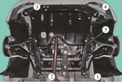
Figure 6-1 - Subframe mounting bolt tightening sequence: 1, 2, 3, 4 - subframe mounting bolts numbered in accordance with tightening order; 5 - front suspension subframe
Place the transmission rack under subframe 5, Figure 6-1, of the front suspension, raise the rack stop until it touches the subframe and unscrew bolts 1 - 4 securing the subframe (replaceable head 18, ratchet, transmission rack type OMA 604, "Avto-spetsoborudovaniye" Pskov).
Lower the transmission rack and remove the front suspension subframe with the front suspension arms, anti-roll bar, steering rack and electric power steering pump assembly. Perform the operation by two performers.
If necessary, disconnect from the subframe:
- anti-roll bar in accordance with the requirements of Section 7 of this TI;
- front suspension arms in accordance with the requirements of Section 5 of this TI;
- steering gear with electric power steering pump and pipelines assembled in accordance with the requirements of TI 3100.25100.20595.
Installation
Caution: Re-use of front suspension subframe mounting bolts is not permitted. Bolts must be replaced.
Caution: Reusing the ball joint mounting nut to the steering knuckle is not permitted. The nut must be replaced.
If removed, install on subframe:
- front suspension arms in accordance with the requirements of Section 5 of this TI;
- anti-roll bar in accordance with the requirements of Section 7 of this TI;
- steering gear with electric power steering pump and pipelines assembled in accordance with the requirements of TI 3100.25100.20595.
Install the subframe on the vehicle and screw in the new mounting bolts without tightening them. The operation must be performed by two performers (18 mm replaceable head, ratchet wrench, OMA 604 transmission rack, "Avtospetsoborudovanie", Pskov).
Finally tighten the subframe mounting bolts in the sequence shown in Figure 6-1. Bolt tightening torque: 105 N·m (10.5 kgf·m) (replaceable head 18, torque wrench).
Attach the rear suspension support rod to the subframe, install the bolt and tighten the mounting nut. Bolt tightening torque 90...120 Nm (9.0...12.0 kgf·m) (ring spanner 16, replaceable head 18, ratchet, torque wrench).
Install the electric power steering pump in place and tighten the three mounting bolts. Tightening torque of bolts 18...24 Nm (0.18...0.24 kgf·m) (replaceable head 13, extension, torque wrench).
Connect the wiring harness connectors from the electric power steering pump.
Connect the ground wire terminal of the power steering electric pump wiring harness and tighten the fastening nut. Nut tightening torque 7...9 Nm (0.7...0.9 kgf·m) (replaceable head 10, ratchet, torque wrench).
Install the steering column intermediate shaft joint fork onto the steering gear pinion shaft and secure with a new bolt and nut. Nut tightening torque 18...24 Nm (0.18...0.24 kgf·m) (replaceable head 13, extension, torque wrench).
Attention. Install the bolt securing the ball joint of the lower arm of the front suspension to the steering knuckle with the head facing the front of the car.
Install the ball joint pin of the front suspension arm into the steering knuckle, install the mounting bolt and tighten the new nut. When assembling, the flange of the spacer washer must fit into the slot on the steering knuckle. Nut tightening torque 62 Nm (6.2 kgf·m) (ring spanner 16, replaceable head 16, ratchet spanner, torque wrench).
Repeat the operation of connecting the lever to the steering knuckle for the other side.
Install the mounting bolts into the upper holes of the front suspension subframe connecting rods and screw them into the corresponding holes of the engine compartment side members. Tightening torque of bolts 21 Nm (2.1 kgf·m) (replaceable head 13, ratchet wrench, torque wrench).
Secure the lower part of the bumper to the front suspension subframe with three mounting screws (torx T30 replacement bit, extension, ratchet wrench).
Install the lower and side mudguards of the front fenders in accordance with the requirements of TI 3100.25100.20599.
Install the engine splash guard and tighten the six mounting bolts. Tightening torque of bolts 18...24 Nm (0.18...0.24 kgf·m) (replaceable head 13, extension, torque wrench).
Install the front wheels in accordance with the requirements of Section 14 of this TI.
Remove the technological fastening belts from the engine cooling system radiator.
Connect the ground wire terminal to the battery (spanner 10).
Place the vehicle on a four-post lift, apply the parking brake and turn off the ignition (four-post platform lift type P-178D-03 with a lifting capacity of 3.5 tons).
Press the front suspension two or three times with your hands.
Finally tighten the nuts of the front suspension arm bolts to the subframe. Tightening torque of nuts 105 Nm (10.5 kgf·m) (ring spanner 18, replaceable head 18 extended, torque wrench).
Check and, if necessary, adjust the front wheel alignment angles in accordance with the requirements of TI 3100.25100.13060.
Present the vehicle to the Quality Control Department. The Quality Control Department will check the vehicle for compliance with the requirements of TU 017200-254-00232934, paragraphs 1.19.19, 1.19.22.