



Removal
Attention: To avoid damaging the front wheel hub bearing, do not:
- loosen and tighten the front wheel hub nut on a vehicle standing on its wheels;
- lower the vehicle onto its wheels with the front wheel drive shaft removed or with the front wheel hub mounting nut loosened.
Place the vehicle on a two-post lift, apply the parking brake and turn off the ignition (electro-hydraulic lift type P-3.2G with a lifting capacity of 3.2 t).
Unlock the steering wheel.
Remove the front wheel in accordance with the requirements of Section 14 of this TI.
In accordance with the requirements of TI 3100.25100.20596:
- remove the front wheel speed sensor;
- disconnect the front brake assembly from the steering knuckle and hang it on the front suspension spring.
Place a stop on the front wheel hub and secure it with two wheel bolts (stop Rou. 604-01, replaceable head 17, ratchet).
Unscrew nut 10, Figure 2-1, fastening the front wheel hub, remove the nut, remove the stop (replaceable head 32, replaceable head 17, ratchet).
In accordance with the requirements of TI 3100.25100.20596:
[Article copied from a web page: Ladaman.ru]
- remove the front brake disc;
- remove the front brake disc cover.
Disconnect the steering rod end from the steering knuckle arm in accordance with the requirements of TI 3100.25100.20595.
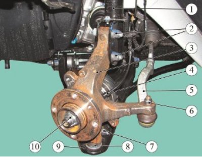
Figure 2-1 - Removing the steering knuckle: 1 - front suspension telescopic strut; 2 - nuts of bolts fastening the steering knuckle to the front suspension strut; 3 - steering knuckle; 4 - front wheel speed sensor; 5 - outer tie rod end; 6 - nut securing the steering rod end to the steering knuckle; 7 - nut of the bolt securing the ball joint to the steering knuckle; 8 - ball joint of the front suspension arm; 9 - front suspension arm; 10 - front wheel hub mounting nut
Loosen nut 7 of the bolt securing the ball joint of the front suspension arm to the steering knuckle and disconnect knuckle 3 from arm 9 (ring spanner 16, replaceable head 16, extension and ratchet).
Remove the spacer washer from the ball joint of the front suspension arm.
Unscrew the two nuts of the 2 bolts securing the steering knuckle to the front suspension strut and remove the bolts (spanner 18, replaceable head 18, ratchet).
Press the drive shaft out of the front wheel hub and remove the steering knuckle with the hub assembly (tav. 1050-04 and Tav. 1420-01 devices).
Installation
Attention: The following fasteners must be replaced:
- front wheel hub mounting nut;
- nut of the bolt of fastening of the ball joint of the front suspension arm;
- nuts of the bolts securing the steering knuckle to the front suspension strut.
Attention. Install the bolt securing the ball joint of the lower arm of the front suspension to the steering knuckle with the head facing the front of the car.
Install the splined tailpiece of the front wheel drive shaft into the front wheel hub.
Install the steering knuckle on the front suspension strut, insert the mounting bolts and tighten the new nuts 2 without tightening (spanner 18, replaceable head 18, ratchet wrench).
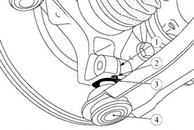
Figure 2-2 - Installing the spacer washer: 1 - slot for terminal connection of steering knuckle and ball joint; 2 - spacer washer flange; 3 - spacer washer; 4 - ball joint of the front suspension arm
Install spacer washer 3 on ball joint pin 4, Figure 2-2, of the front suspension arm.
Install the ball joint pin of the front suspension arm into the steering knuckle, install the mounting bolt and tighten the new nut. During assembly, flange 2 of spacer washer 3 must fit into slot 1 of the terminal connection on the steering knuckle. Nut tightening torque 62 Nm (6.2 kgf·m) (spanner 16, replaceable head 16, ratchet wrench, torque wrench).
Tighten the nuts of the bolts securing the steering knuckle to the front suspension strut. Tightening torque of nuts 105 Nm (10.5 kgf·m) (spanner 18, replaceable head 18, torque wrench).
Connect the steering rod end to the steering knuckle arm in accordance with the requirements of TI 3100.25100.20595.
In accordance with the requirements of TI 3100.25100.20596:
- install front brake disc cover;
- install the front brake disc.
Place a stop on the front wheel hub and secure it with two wheel bolts (stop Rou. 604-01, replaceable head 17, ratchet).
Tighten the new front wheel hub mounting nut and remove the stop. Nut tightening torque 280 N·m (28.0 kgf·m) (replaceable head 17, replaceable head 32, ratchet, torque wrench).
In accordance with the requirements of TI 3100.25100.20596:
- install front wheel speed sensor;
- install the front brake assembly.
Install the front wheel in accordance with the requirements of Section 14 of this TI.
Press the brake pedal 2 - 3 times to set the wheel brake cylinder pistons to the working position.
Check and, if necessary, adjust the front wheel alignment angles in accordance with the requirements of TI 3100.25100.13060.
Present the vehicle to the Quality Control Department. The Quality Control Department will check the vehicle for compliance with the requirements of TU 017200-254-00232934, paragraphs 1.19.19, 1.19.22.