



Removal
Place the vehicle on a two-post lift, apply the parking brake and turn off the ignition (electro-hydraulic lift type P-3.2G with a lifting capacity of 3.2 t).
Remove the front wheel in accordance with the requirements of Section 14 of this TI.
Remove the front wing side mudguard in accordance with the requirements of TI 3100.25100.20599.
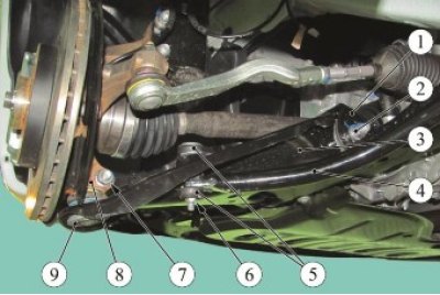
Figure 5-1 - Removing the front suspension arm: 1 - front suspension subframe; 2 - nut of the rear bolt securing the lever to the subframe; 3 - front suspension arm; 4 - Anti-roll bar link; 5 - Anti-roll bar link; 6 - nut of the stabilizer bar mounting bolt; 7 - nut of the bolt securing the ball joint to the steering knuckle; 8 - steering knuckle; 9 - ball joint
Loosen nut 6, Fig. 5-1, of the bolt securing the anti-roll bar to arm 3 of the front suspension (torx T40 angle wrench, 13 mm replaceable head, ratchet wrench).
Remove the stabilizer bar components from the front suspension arm: the lower rubber-metal hinge, the mounting bolt, two rubber bushings, the upper rubber-metal hinge and the washer.
Loosen nut 7 of the bolt securing the ball joint of the front suspension arm to the steering knuckle and disconnect arm 3 from knuckle 8 (ring spanner 16, replaceable head 16, extension and ratchet).
Loosen and remove bolt 1, Figure 5-2, securing the front suspension subframe brace to the engine compartment side member (replaceable head 13, ratchet wrench).
Loosen nut 4 securing the front suspension subframe tie rod to the front suspension arm and remove rod 2 (ring spanner 18, replaceable head 18, ratchet spanner).
Loosen the nuts of the bolts securing the lower arm of the front suspension to the subframe, remove the bolts and remove arm 6 (ring spanner 18, replaceable head 18 extended, ratchet spanner).
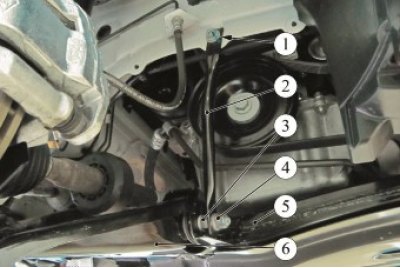
Figure 5-2 - Removing the front suspension subframe strut: 1 - bolt for fastening the subframe tie rod to the side member; 2 - front suspension subframe stretcher; 3 - nut of the front suspension arm mounting bolt; 4 - nut securing the subframe tie rod to the front suspension arm; 5 - front suspension subframe; 6 - front suspension arm
Installation
Caution: Reuse of front suspension arm mounting bolts and nuts is not permitted. Bolts and nuts must be replaced.
Caution: Reusing the ball joint mounting nut to the steering knuckle is not permitted. The nut must be replaced.
Attention. Install the bolts securing the front suspension arm to the subframe with the heads facing the inner part of the arm.
Attention. Install the bolt securing the ball joint of the lower arm of the front suspension to the steering knuckle with the head facing the front of the car.
Install the lower arm of the front suspension on the subframe, install the mounting bolts and tighten the nuts without tightening them (ring spanner 18, replaceable head 18 extended, ratchet spanner).
Install the ball joint pin of the front suspension arm into the steering knuckle, install the mounting bolt and tighten the new nut. When assembling, the flange of the spacer washer must fit into the slot on the steering knuckle. Nut tightening torque 62 Nm (6.2 kgf·m) (ring spanner 16, replaceable head 16, ratchet spanner, torque wrench).
Install the anti-roll bar strut elements on the lever: washer, upper rubber-metal hinge, install two rubber bushings between the lever and the stabilizer, install the mounting bolt, lower rubber-metal hinge, tighten the package of strut elements with a clamp and tighten the nut. Nut tightening torque 14 Nm (1.4 kgf·m) (clamp Sus. 1413 and Sus. 1734, Torx T40 angle key, replaceable head 13, ratchet key, torque wrench).
Install the subframe brace in place and tighten the bolt securing the rod to the side member and the nut securing the rod to the front suspension arm. Tightening torques for bolts 62 N·m (6.2 kgf·m), nuts 62 N·m (6.2 kgf·m) (replaceable head 13, 18, ratchet wrench, torque wrench).
Install the front wing side mudguard in accordance with the requirements of TI 3100.25100.20546.
Install the front wheel in accordance with the requirements of Section 14 of this TI.
Place the vehicle on a four-post lift, apply the parking brake and turn off the ignition (four-post platform lift type P-178D-03 with a lifting capacity of 3.5 tons).
Press the front suspension two or three times with your hands.
Finally tighten the nuts of the front suspension arm bolts to the subframe. Tightening torque of nuts 105 Nm (10.5 kgf·m) (ring spanner 18, replaceable head 18 extended, torque wrench).
Check and, if necessary, adjust the front wheel alignment angles in accordance with the requirements of TI 3100.25100.13060.
Present the vehicle to the Quality Control Department. The Quality Control Department will check the vehicle for compliance with the requirements of TU 017200-254-00232934, paragraphs 1.19.19, 1.19.22.