



Removal
Place the vehicle on a two-post lift, apply the parking brake and turn off the ignition (electro-hydraulic lift type P-3.2G with a lifting capacity of 3.2 t).
Remove the front wheel in accordance with the requirements of Section 14 of this TI.
In accordance with the requirements of TI 3100.25100.20596:
- remove the front wheel speed sensor;
- disconnect the front brake assembly from the steering knuckle and hang it on the front suspension spring;
- remove the front brake disc;
- remove the front brake disc cover.
Disconnect the steering rod end from the steering knuckle arm in accordance with the requirements of TI 3100.25100.20595.
Remove the steering knuckle in accordance with the requirements of Section 2 of this TI.
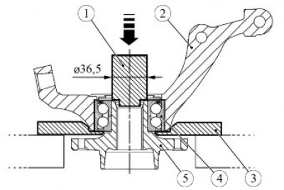
Figure 3-1 - Pressing out the front wheel hub: 1 - mandrel with an outer diameter of 36.5 mm for pressing out the hub; 2 - steering knuckle; 3 - support plate; 4 - Front wheel hub bearing; 5 - front wheel hub
Install support plate 3 on the press table, Figure 3-1, install steering knuckle 2 on the plate, install mandrel 1 with an outer diameter of 36.5 mm on the hub and press out hub 5 from the steering knuckle (hydraulic press type KS-124 (Kochubeyevsky Plant "Avtospetsoborudovaniye"), mandrel with an outer diameter of 36.5 mm for pressing out the hub - self-made, support plate - self-made).
Remove the bearing retaining ring from the steering knuckle (internal retaining ring puller type 65 44 60 21 size J 21 from "Stahlwille").
Press the inner bearing race off the hub (set of pullers type 71 03 00 00 and 71 04 00 00 from "Stahlwille").
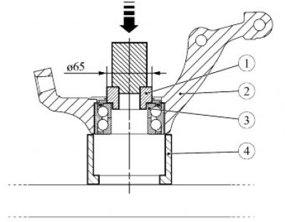
Figure 3-2 - Pressing out the outer race of the front wheel hub bearing from the steering knuckle: 1 - a mandrel with an outer diameter of 65 mm for pressing out the outer race of the front wheel hub bearing; 2 - steering knuckle; 3 - inner bearing race; 4 - stop
Install stop 4 on the press table, Figure 3-2, install steering knuckle 2 on the stop, install mandrel 1 with an outside diameter of 65 mm on the inner race 3 of the bearing and press out the outer bearing ring from the steering knuckle (hydraulic press type KS-124 (Kochubeyevsky Plant "Avtospetsoborudovaniye"), mandrel with an outside diameter of 65 mm for pressing out the outer bearing ring - self-made, stop - self-made).
Installation
Caution: Before assembly, clean the mating surfaces of the steering knuckle, front wheel hub and bearing.
Attention. Before assembly, check the seating surfaces of the steering knuckle and front wheel hub, replace defective parts.
Attention: When pressing the bearing into the steering knuckle, apply the pressing force to the outer race of the bearing. Pressing by acting on the inner bearing race is not permitted.
Install stop 4 on the press table, Figure 3-3, install steering knuckle 3 on the stop and press in the bearing, installing mandrel 1 with an outside diameter of 70 mm for pressing in on the outer race 2 of the bearing (hydraulic press type KS-124 (Kochubeyevsky Plant "Avtospetsoborudovaniye"), mandrel with an outside diameter of 65 mm for pressing in the bearing - self-made, stop - self-made).
Install a retaining ring into the groove of the knuckle (retaining ring puller type 65 44 60 21 size J 21 from "Stahlwille").
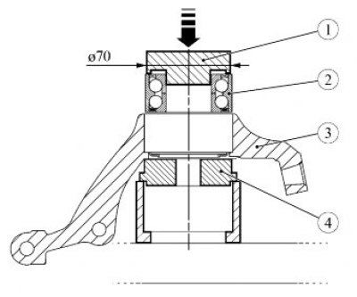
Figure 3-3 - Pressing the front wheel hub bearing into the steering knuckle: 1 - mandrel with an outer diameter of 70 mm for pressing in the front wheel hub bearing; 2 - outer bearing race; 3 - steering knuckle; 4 - stop
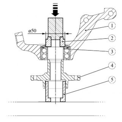
Figure 3-4 - Pressing in the front wheel hub: 1 - steering knuckle; 2 - mandrel with an outer diameter of 50 mm for pressing the front wheel hub; 3 - inner bearing race; 4 - front wheel hub; 5 - emphasis
Place the stop 5 on the press table, Figure 3-4, place the hub 4 of the front wheel on the stop and press the knuckle 1 with the bearing assembly onto the hub, installing the mandrel 2 with an outer diameter of 50 mm for pressing on the inner race 3 of the bearing (hydraulic press type KS-124 (Kochubeyevsky Plant "Avtospetsoborudovaniye"), the mandrel with an outer diameter of 50 mm for pressing - self-made, the stop - self-made).
Install the steering knuckle on the vehicle in accordance with the requirements of Section 2 of this TI.
Connect the steering rod end to the steering knuckle arm in accordance with the requirements of TI 3100.25100.20595.
In accordance with the requirements of TI 3100.25100.20596:
- install front brake disc cover;
- install front brake disc;
- install front brake assembly;
- install the front wheel speed sensor.
Install the front wheel in accordance with the requirements of Section 14 of this TI.
Press the brake pedal 2-3 times to set the wheel brake cylinder pistons to the working position.
Check and, if necessary, adjust the front wheel alignment angles in accordance with the requirements of TI 3100.25100.13060.
Present the vehicle to the Quality Control Department. The Quality Control Department will check the vehicle for compliance with the requirements of TU 017200-254-00232934, paragraphs 1.19.19, 1.19.22.