



Removal
Place the vehicle on a two-post lift, apply the parking brake and turn off the ignition (electro-hydraulic lift type P-3.2G with a lifting capacity of 3.2 t).
Remove the front wheel in accordance with the requirements of Section 14 of this TI.
Unlock the steering wheel.
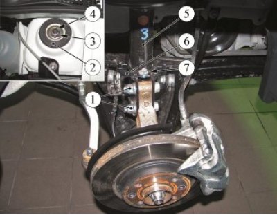
Figure 4-1 - Removing the front suspension strut: 1 - nuts of bolts fastening the steering knuckle to the front suspension strut; 2 - upper cup of the front suspension strut; 3 - nut securing the front suspension strut rod to the car body; 4 - front suspension strut rod; 5 - telescopic strut of the front suspension; 6 - Speed sensor wiring harness holder; 7 - wiring harness holder mounting bolt
Remove the front wheel speed sensor wiring harness from the holder 6, Figure 4-1, on the front suspension strut.
Loosen bolt 7 securing the speed sensor wiring harness holder to the front suspension strut and remove holder 6 (replacement head 10, ratchet wrench).
Disconnect the front brake assembly from the steering knuckle in accordance with the requirements of TI 3100.25100.20596 and secure it to the lower arm of the front suspension.
Unscrew the two nuts 1 of the bolts securing the steering knuckle to the front suspension strut, remove the boots and disconnect the strut 5 from the steering knuckle (spanner 18, replaceable head 18, ratchet).
Secure the steering knuckle to the car body.
Loosen nut 3 securing rod 4 of the front suspension strut to the car body (ring spanner 21, hexagonal angle 6).
Remove the upper cup 2 of the front suspension strut.
Remove the front suspension strut 5.
Install the front suspension strut in the strut disassembly device, compress the spring until the outer spring turns move away from the strut support cups and unscrew nut 5, Figure 4-2, fastening the upper strut support (strut disassembly device KT01-22 (PKF "TEP", Irkutsk) or spring compression device type 12625 code 96 71 06 00 of the company "Stahlwille", ring spanner 27, angular hexagon 6).
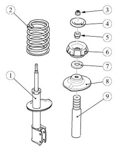
Figure 4-2 - Front suspension telescopic strut assembly: 1 - front suspension telescopic strut; 2 - front suspension spring; 3 - nut securing the front suspension strut rod to the car body; 4 - upper cup of the front suspension strut; 5 - upper support mounting nut; 6 - upper support of the front suspension strut; 7 - Upper support bearing; 8 - upper spring support cup; 9 - compression stroke buffer
Remove the upper support 6, the upper support bearing 7 and the upper support cup 8 of the spring from the strut 1 of the front suspension.
Unload and remove spring 2 and compression stroke buffer 9 from the rack.
Installation
Attention: Check the condition of the front suspension strut parts and replace if necessary.
Attention: The following fasteners must be replaced:
- upper strut support mounting nut;
- nut for fastening the front suspension strut rod to the car body;
- nuts of the bolts securing the steering knuckle to the front suspension strut.
Attention. When assembling the front suspension strut, check the position of the outer spring coils relative to the profile of the support cups. The spring should be positioned in the grooves of the support cups as shown in Figure 4-3.
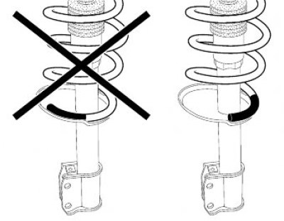
Figure 4-3 - Position of the outermost spring coil in the support cup
Install the compression buffer 9 and spring on the front suspension strut 1.
Compress spring 2 (device for disassembling struts KT01-22 (PKF "TEP", Irkutsk) or device for compressing springs type 12625 code 96 71 06 00 of the company "Stahlwille").
Install the upper support cup 8 of the spring, bearing 7, upper support 6 on the rack and tighten nut 5. The tightening torque of the nut is 62 N·m (6.2 kgf·m) (hexagonal hexagon 6, ring spanner 27, replaceable insert 27 type 58 22 40 27 from "Stahlwille", torque wrench type 50 18 00 12 company "Stahlwille").
Unload the spring.
Install the front suspension strut on the vehicle, install the upper cup 4 of the strut and tighten nut 3 onto the strut rod. The tightening torque of the nut is 44 N·m (4.4 kgf·m) (hexagonal hexagon 6, ring spanner 21, replaceable insert 21 type 58 22 40 21 of the company "Stahlwille", torque wrench type 50 18 00 12 company "Stahlwille").
Connect the strut to the steering knuckle, insert the mounting bolts and tighten the nuts. Tightening torque of nuts 105 Nm (10.5 kgf·m) (spanner 18, replaceable head 18, ratchet, torque wrench).
Install the front brake assembly on the steering knuckle in accordance with the requirements of TI 3100.25100.20596.
Install the speed sensor wiring harness holder onto the front rack and secure with a bolt (replacement head 10, ratchet wrench).
Install the speed sensor wiring harness into the bracket on the front suspension strut.
Install the front wheel in accordance with the requirements of Section 14 of this TI.
Press the brake pedal 2 - 3 times to set the wheel brake cylinder pistons to the working position.
Check and, if necessary, adjust the front wheel alignment angles in accordance with the requirements of TI 3100.25100.13060.
Present the vehicle to the Quality Control Department. The Quality Control Department will check the vehicle for compliance with the requirements of TU 017200-254-00232934, paragraphs 1.19.19, 1.19.22.