



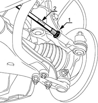
Figure 10 - Adjusting the front wheel alignment of LADA LARGUS R90 and F90 vehicles: 1 - wheel alignment lock nut; 2 - steering linkage coupling
Table 1
| Car model | Tire size | Air pressure in tires, MPa (kgf/cm²) | |
| front wheels | rear wheels | ||
| LADA Largus R90 | 185/70 R14, 185/65 R15 | 0,24=0,01 (2,4=0,1) | 0,26=0,01 (2,6=0,1) |
| LADA Largus F90 | 185/65 R15 | 0,24=0,01 (2,4=0,1) | 0,30=0,01 (3,0=0,1) |
Table 2
| Car model | Front wheel alignment angles: | |||||||
| Car under load | Equipped vehicle | |||||||
| Wheel alignment, deg. | Angle of longitudinal inclination of the wheel steering axis, deg. | Wheel alignment: | Wheel alignment, deg. | Angle of longitudinal inclination of the wheel steering axis, deg. | Wheel alignment: | |||
| Linear, mm | Angular, deg. | Linear, mm | Angular, deg. | |||||
| R90, F90 | - | - | - | - | -0°10=40' | 2°42' ±30' * | - | -0°40'..0°20' |
Table 3
| Rear wheel alignment angles of the equipped vehicle | ||
| Car model | Wheel alignment, deg. | Wheel alignment, deg. |
| LADA Largus R90, F90 | -0°51±15' | +0°44' ±15' |
1. On LADA R90 and F90 vehicles, the longitudinal tilt angle of the steering axis and the camber of the front wheels are built into the vehicle design and are not subject to adjustment. The angle values are provided in Table 2 for reference. If the parameter values given in the table deviate, check the front suspension parts and the suspension attachment points to the body. If necessary, replace damaged parts of the front suspension and eliminate deviations in body geometry.
2. Adjust the front wheel alignment of LADA R90 and F90 vehicles.
2.1. Set the steering wheel to the straight-ahead position.
2.2. Loosen the tightening of the lock nuts 1, Fig. 10, holding the couplings 2 of the steering rods with a wrench (spanners 13, 21).
2.3. By turning couplings 2, set the lengths of the steering rods at which the toe-in of the front wheels will correspond to the parameters given in Table 2. After adjusting the lengths of the steering rods, the steering wheel should be in a position corresponding to straight-line movement (spanner 13).
2.4. Tighten the locknuts 1 of the steering linkage rods. Tightening torque of lock nuts 50 N·m (5.0 kgf·m) (spanners 13, 21, torque wrench and replaceable insert type 819B21 f. USAG).
2.5. Check the front wheel alignment angles. The values of the front wheel alignment angles are given in Table 2. When checking under load, the applied load should be: - 320±5 kgf. Conduct the check according to the operating instructions for the device. If the values of the parameters given in Table 2 deviate, adjust them.
About the rear wheel alignment angles
The rear wheel alignment angles on Largus are not adjustable. This is not provided for by either the regulations or the design of the vehicle. But they can be measured! (see table above) And in view of the fact that many cars have broken corners (for various reasons), car owners use a method that involves placing 2 washers of the required thickness (thickness is selected individually), between the brake shield and the rear beam, on the side that is individual for each specific case.
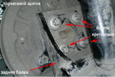
The algorithm is roughly as follows: the wheel alignment is measured (or simply assessed independently based on uneven tire wear). It is determined which bolts need to be unscrewed to insert the washers, and the thickness of the washers is roughly estimated.
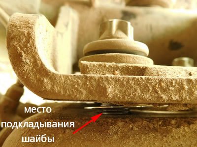
They remove the wheel. There is no need to remove the hub. A Torx E16 head is used to open the brake shield bolts. They are unscrewed (but not completely) all four bolts. The shield is moved away from the beam as far as the bolts allow. Only the two bolts on the side where the washers will be placed are completely unscrewed. The bolts are pulled out, washers are inserted using a thin tool (see photo), and the bolts are inserted into place. Everything is coming together. And again the wheel alignment is measured. If adjustment is necessary, the procedure is repeated.