
The discrepancy between the actual values measured on the car and the control values indicated below is due to wear and deformation of the suspension parts, deformation of the body.
Attention! Replacing or repairing suspension parts may entail a change in wheel alignment, so checking the wheel alignment after carrying out these works is mandatory.
Note. Check wheel alignment on a vehicle with a half-full fuel tank, with 70 kg of ballast on each front seat.
Vehicle wheel alignment angles in running order:
- camber — 0°±30'
- convergence - (0±1,0) mm
- angle of longitudinal inclination of the axis of rotation — 1°30'±30'
Attention! The difference in pitch angle between the right and left wheels must not exceed 1°.
Before wheel alignment check:
- air pressure in tires;
- radial and axial runout of wheel disks, which should not exceed 0.7 and 1 mm, respectively;
- free play (backlash) steering wheel;
- free play (backlash) in the bearings of the front wheel hubs;
- technical condition of parts and suspension units (absence of deformations, destruction and wear of rubber-metal hinges, unacceptable settlement of the upper support of the suspension strut).
Eliminate the observed faults.
After installing the car on the stand (just before corner control) «press» car suspension, applying two or three times a force of 392–490 N (40–50 kgf), directed from top to bottom, first at the rear bumper, and then at the front. In this case, the wheels of the car must be parallel to the longitudinal axis of the car.
Note. When adjusting the wheel alignment, first adjust the caster angle and then the camber and toe.
Angle of longitudinal inclination of the axis of rotation
If the angle does not match the data above, change the number of shims installed on both ends of the suspension braces. To increase the angle of the longitudinal inclination of the axis of rotation, reduce the number of washers on the brace in the front or rear of it. Conversely, to reduce the angle, add the number of washers, but only in the back of the guy, since in front this is not always possible due to the short threaded part of the guy.
When changing the number of washers on the brace, make sure that the chamfers on the washers face the thrust end of the brace. Observe this rule also when installing the internal thrust washer of the rubber-metal hinge, when the adjusting washers are completely removed. If these requirements are not observed, the tightening of the nuts for fastening the guy wires may loosen.
The number of shims on the extension should not be more than two in front and four in the back.
In order not to change the position of the brace relative to the suspension arm when adjusting the longitudinal inclination of the axis of rotation, use a special device that fixes the brace relative to the lever, thereby preventing the brace from turning due to forces when tightening the brace nut to the arm. This requirement must be observed in order to prevent premature wear of the rubber-metal hinge and the rubber cushion, on which the ends of the extension rest.
When installing or removing one shim, the caster angle of the steering axis changes by approximately 19'.
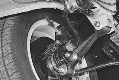
Front camber angle
If the camber angle is out of specification, adjust it.
To do this, loosen the nuts of the upper and lower bolts and, by turning the upper adjusting bolt, set the desired camber angle. At the end of the adjustment, tighten the nuts to a torque of 88.2 Nm (9 kgf·m).
Front wheel alignment
If alignment is not correct..
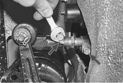
...loosen with a key «at 13» tie rod end pins..
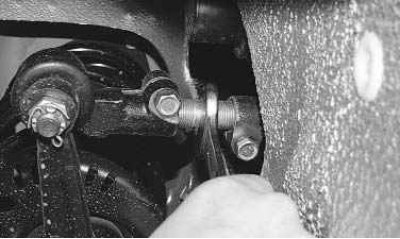
... and, turning the key «at 22» adjusting rods, set the required convergence. Then make sure that the plane of the ball joint is parallel to the plane of the pivot arm bearing surface, then tighten the tie rod end pinch bolts to 19.1-30.9 Nm (1.95–3.15 kgf·m).