



Cable clutch (for gearbox JH3)
The cable clutch drive does not have an automatic clearance compensation mechanism.
Single-disc, dry, with central diaphragm spring. The mechanism is located in an aluminum crankcase, structurally integrated with the gearbox and attached to the engine cylinder block.
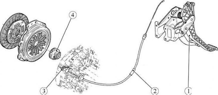
1 - clutch pedal; 2 - clutch drive cable; 3 - clutch release fork; 4 - clutch release bearing
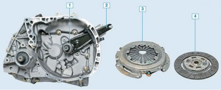
1 – clutch release bearing with clutch assembly; 2 – clutch release fork; 3 – pressure plate with housing assembly ("clutch basket"); 4 – driven disk
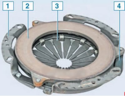
Clutch basket (pressure plate assembly): 1 – clutch housing; 2 – pressure plate; 3 – diaphragm spring; 4 – connecting plates
The clutch housing is connected to the engine flywheel with six bolts. The "basket" needs to be replaced if the diaphragm spring petals are worn annularly to a depth of more than 0.8 mm, and also if the pedal force decreases when disengaging the clutch (and, accordingly, an increase in the working stroke), which indicates significant wear on the surface of the pressure plate or "settling" of the diaphragm spring.
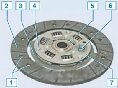
Clutch slave disc: 1 – friction lining rivet; 2 – friction linings; 3 – spring plate; 4 – support finger; 5 – disk hub; 6 – damper spring; 7 – damper plate
The driven disk with a spring torsional vibration damper is mounted on the splines of the primary shaft of the gearbox between the flywheel and the pressure plate.
The outer diameter is 200 mm, thickness is 7.6 mm. The driven disk is replaced if its axial runout in the friction lining area is more than 0.5 mm, if there is oiling, cracking, scoring or uneven wear of the linings, if the riveted joints are loosened, and also if the rivet heads are recessed from the lining surface by less than 0.2 mm.
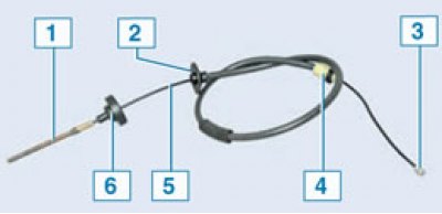
Clutch cable: 1 – front cable end; 2 – front end of the cable sheath; 3 – rear cable end; 4 – rear end of the cable sheath; 5 – cable; 6 – rubber support bushing
The front end of the cable is secured to the clutch release fork, and the rear end is secured to the clutch pedal holder. The front end is threaded and is used to adjust the clutch release drive.
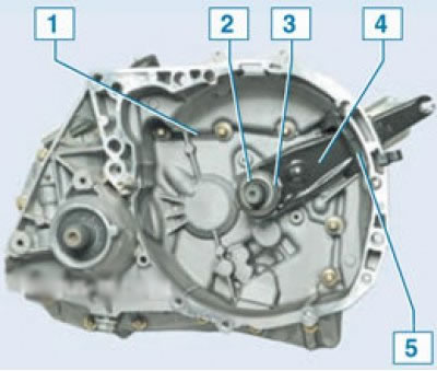
Clutch drive parts: 1 – clutch housing; 2 – Clutch release bearing guide sleeve; 3 – clutch release bearing with clutch assembly; 4 – clutch release fork; 5 – mudguard
Hydraulic clutch (for gearbox JR5)
The clutch release drive is hydraulic. The force from the clutch pedal to the clutch release bearing is transmitted through the working fluid. The hydraulic drive consists of the main and working clutch cylinders, connected by a pipeline. The working fluid is poured into a reservoir, which is installed on the main brake cylinder and is used to supply the brake system and the clutch release drive.
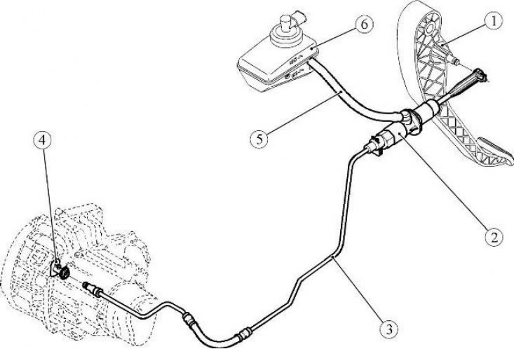
1 - clutch pedal; 2 - clutch master cylinder; 3 - pipeline connecting the master and slave cylinders of the clutch drive; 4 - clutch drive slave cylinder; 5 - clutch master cylinder supply line; 6 - brake hydraulic fluid reservoir
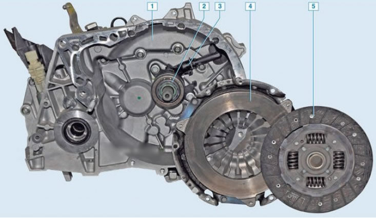
1 – clutch housing; 2 – clutch release bearing; 3 – clutch release slave cylinder; 4 – pressure plate with housing assembly ("basket"); 5 – driven disk
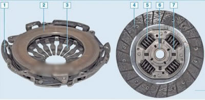
"Basket" and driven clutch disc: 1 – casing; 2 – pressure plate; 3 – diaphragm spring; 4 – friction linings; 5 – damper springs; 6 – driven disk hub; 7 – damper
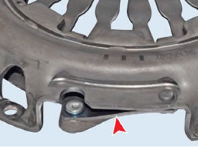
Elastic plates. The casing contains a diaphragm spring, which is stamped from sheet spring steel. In a free state, the spring has the form of a truncated cone with radial slots extending from the inner edge of the spring. The spring slots form eighteen petals, which are elastic release levers. Due to the elasticity of the levers, the diaphragm spring creates a more uniform pressure on the clutch pressure plate, which contributes to smoother engagement and disengagement of the clutch.
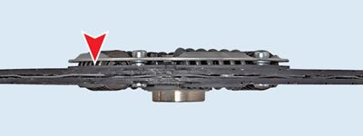
The arrangement of the wave spring plate. The driven disk with a spring-loaded torsional vibration damper is mounted on the splines of the primary shaft of the gearbox between the engine flywheel and the pressure plate.
The torsional vibration damper dampens vibrations arising from dynamic loads in the transmission and uneven engine operation.
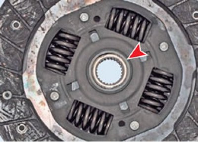
Idle damper. A disc hub is installed between the damper plates. The damper springs are installed in the grooves of the hub and damper plates. The damper plates are connected by support pins. In the hub of the disc opposite the support posts there are cutouts that allow the hub to rotate within certain limits relative to the damper plates, thereby compressing the damper springs. This allows to reduce dynamic loads in the transmission when starting the car and changing gears.
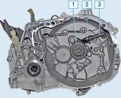
Clutch release bearing: 1 – bearing; 2 – working cylinder; 3 – pipe for supplying liquid to the working cylinder
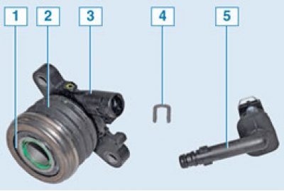
Details of the slave cylinder and clutch release bearing: 1 – clutch release bearing; 2 – protective cover; 3 – working cylinder; 4 – retainer; 5 – pipe for supplying liquid to the working cylinder
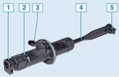
Clutch Master Cylinder: 1 – nipple for connecting the hydraulic drive tube; 2 – master cylinder body; 3 – nipple for connecting the hose for supplying liquid from the tank; 4 – pusher; 5 – pusher tip
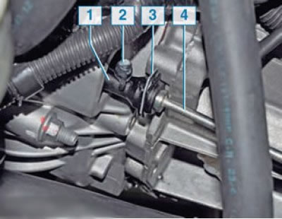
Clutch hydraulic drive bleed nipple: 1 – liquid supply pipe to the working cylinder; 2 – bleed nipple; 3 – retainer; 4 – clutch hydraulic tube
To bleed the clutch hydraulic drive, there is a nipple on the plastic tube that supplies fluid to the working cylinder, covered with a rubber cap.