



Note: If the clutch fails, we recommend replacing all of its components at the same time (driven and driving discs, clutch release bearing), since the work of replacing the clutch is labor-intensive, and the service life of undamaged clutch elements has already been reduced, therefore, if they are reinstalled, it may be necessary to replace the clutch again after a relatively short mileage.
Part numbers are listed here (8th grade) and here (16th grade).
Clutch device see here.
The work on K4M and K7M engines to replace the clutch is no different.
To do this, you will need a mandrel for centering the driven clutch disc.
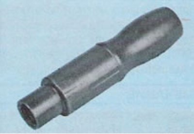
The mandrel from VAZ cars is suitable. (Original - Emb. 1518 or Emb. 1780, or 67.7823-9702 L)
Removal
Place the vehicle on a two-post lift, apply the parking brake, turn off the ignition, open the hood and disconnect the ground wire from the battery.
Remove the gearbox (see here).
Note: When replacing the clutch, you don't have to remove the gearbox completely, just move it away from the engine to the required distance. This work is shown here.
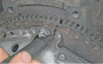
Tip: If you are going to install the old pressure plate, mark it in any way (for example, with a marker) the relative position of the disc casing and the flywheel to set the pressure plate to its previous position (to maintain balance).
If available, install a flywheel lock on the engine block (flywheel locking tool Mot. 582-01).
If not, use a screwdriver or a mounting blade to hold the flywheel from turning and...
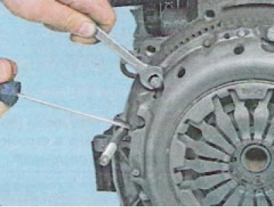
... unscrew the six bolts 1, Figure 3-1, securing the clutch pressure plate to the flywheel and remove the pressure 2 and driven clutch plates (replacement head 13, extension, ratchet).
Loosen the bolts evenly: each bolt by one turn of the wrench, moving from bolt to bolt according to diameter.
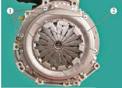
Figure 3-1 - Removing the clutch: 1 - pressure plate mounting bolt; 2 - clutch pressure plate
Remove the pressure and driven clutch discs from the flywheel, holding the driven disc.
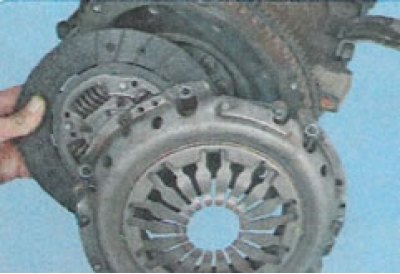
Checking the driven clutch discs
Driven clutch discs for vehicles with K4M and K7M engines have different damper spring stiffness. To distinguish the driven clutch discs, marks are applied with paint to the damper springs, Figure 3-2.
Differences between driven clutch discs:
| Parameters | Engine K4M | Engine K7M |
| Outside diameter of driven disk, mm | 200 | 200 |
| Thickness of driven disk, mm | 7,5 | 7,6 |
| Number of splines | 26 | 26 |
| Color of spring marks (figure 3-2) | 1 - gray; 2 - green; 3 - blue-lilac | grey |
Inspect the driven clutch disc.
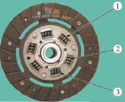
Figure 3-2 - Clutch slave disk marks on a vehicle with a K4M engine: 1 - gray; 2 - green; 3 - blue-lilac
If there are cracks, dents, breaks in the damper springs and cracks or delamination of the friction linings, the disc must be replaced.
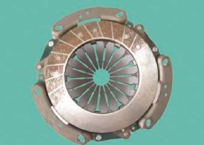
Figure 3-3 - Clutch pressure plate
Preparing for installation
Check the surface of the engine flywheel that contacts the driven clutch disc. There should be no scratches or traces of tarnish on the surface of the flywheel.
Check for jamming of the engine crankshaft main bearing.
Check the tightness of the engine and gearbox seals and replace if necessary.
Check the free movement of the clutch driven disc along the input shaft.
Check for signs of wear on the clutch engagement bearing guide sleeve and clutch engagement fork.
Clean and wash the flywheel surface in contact with the driven clutch disc, the splines of the gearbox input shaft and the splines in the driven disc hub (white spirit, consumption rate 10 g).
Installation
Before installation, check the ease of movement of the driven disk along the splines of the gearbox input shaft; apply high-melting consistent grease to the splines of the driven disk hub.
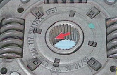
Note: Install the driven disc so that the protruding part of the disc hub (shown by arrow) was directed towards the diaphragm spring of the clutch housing.
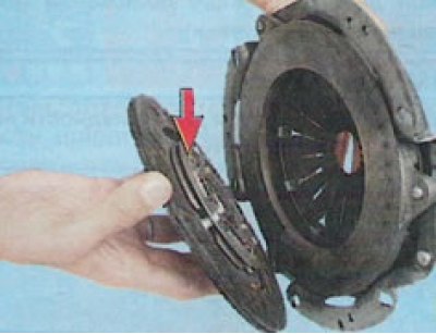
Install the clutch assembly onto the flywheel without tightening the bolts 1, Figure 3-1, securing the pressure plate (replaceable head 8, ratchet and extension).
Install mandrel 1, Figure 3-4, into the driven disk hub and center the driven clutch disk relative to the flywheel.
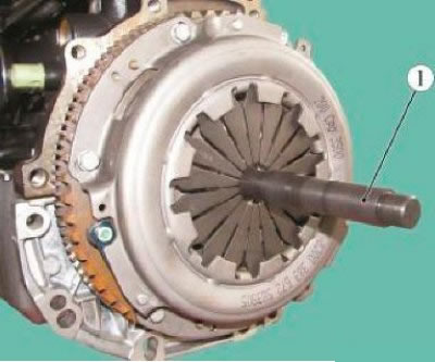
Figure 3-4 - Centering the Clutch Driven Disc: 1 - mandrel for centering the driven clutch disc
Tighten the bolts 1, Figure 3-1, of the clutch pressure plate fastening alternately in a crosswise pattern. (replaceable head 13, extension, ratchet, torque wrench):
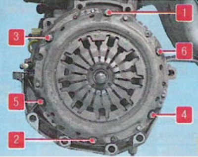
Clutch bolt tightening sequence
The tightening torque of the clutch pressure plate mounting bolts is 20 Nm (2.0 kgf·m).
Remove the flywheel lock (if any).
Install the gearbox.
After installing the gearbox, check the stroke of the clutch release fork (for vehicles with cable drive) and the absence of air in the clutch hydraulic drive (for vehicles with hydraulic drive).
If necessary, adjust the clutch release fork stroke (for vehicles with cable drive) or remove air from the clutch hydraulic system (for vehicles with hydraulic drive (JR5)).