
Removing
Put the car on a two-post lift, apply the parking brake, turn off the ignition, open the hood.
Remove the battery.
Remove the battery tray.
For vehicles with K4M engine
Remove intake silencer.
Operations for all vehicle configurations
Remove the ECM.
Disconnect the wiring harness from the transmission.
Disconnect the wiring harness from the ECM bracket.
Set aside the engine wiring harness.
Loosen two nuts 1, Figure 2-3, fixing the expansion tank (wrench).
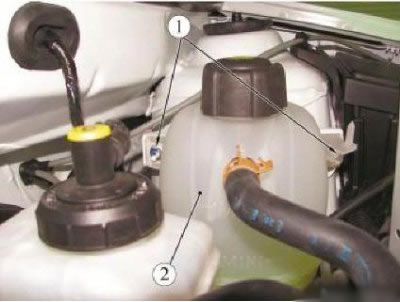
Figure 2-3 - Detaching the expansion tank: 1 - expansion tank nut; 2 - expansion tank
Remove expansion tank 2 and lay aside without disconnecting hoses.
Disconnect connector 1, Figure 2-4, of the ignition harness from the vehicle speed sensor.
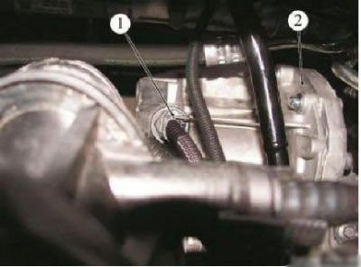
Figure 2-4 - Disconnecting the ignition harness from the vehicle speed sensor: 1 - block of the wiring harness to the vehicle speed sensor; 2 - gearbox
For vehicles with JR5 gearbox
Disconnect the hinges 1, Figure 2-5, of the selector and shift cables from the gearbox levers 2 (flat screwdriver).
Disconnect the stoppers 3 of the sheaths of the select and shift cables from the brackets on the gearbox by pressing the tabs on both sides.
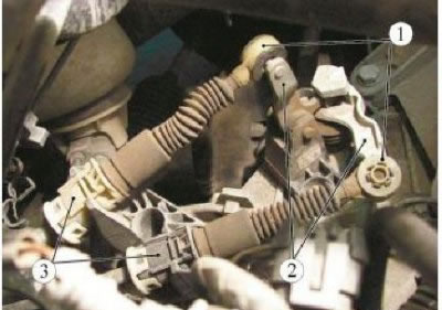
Figure 2-5 - Disconnecting the select and shift cables from the gearbox: 1 - cable hinge; 2 - gear lever; 3 - cable sheath stopper
Disconnect the pipeline 1, Figure 2-6, of the clutch hydraulic drive from the working cylinder 2 by pressing the lock 4.
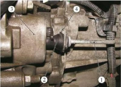
Figure 2-6 - Disconnecting the clutch hydraulic pipeline from the slave cylinder: 1 - clutch hydraulic pipeline; 2 - working cylinder of the hydraulic clutch; 3 - gearbox; 4 - latch
Attention! Do not pull on the latch, this can lead to failure of the hydraulic drive connector. If it fails, replace the pipeline.
Open the lid of the brake and clutch fluid reservoir and drain the brake fluid from the reservoir (technological capacity).
Plug pipe openings (technological plugs).
For vehicles with JH3 gearbox
Move away the protective cover 1, Figure 2-7, gear shift rods.
To turn away a bolt 2 fastenings of draft of a drive of a gear change (interchangeable head 10, extension, crank).
Fix the linkage 3 of the gearshift drive to the body (technological hook).
Disconnect the clutch cable 1, Figure 2-8, from the clutch release fork 2.
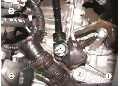
Figure 2-7 - Disconnecting the transmission control drive linkage: 1 - protective cover for the gear lever; 2 - a bolt of fastening of draft of a drive of management of a transmission; 3 - thrust of the gearbox control drive
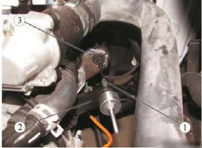
Figure 2-8 - Disconnecting the clutch cable from the gearbox: 1 - clutch cable; 2 - clutch release fork; 3 - clutch cable sheath stopper
Disconnect the clutch cable from the clutch cable sheath retainer.
Operations for all vehicle configurations
Remove front wheels.
Raise the vehicle to a comfortable working height.
Remove the engine crankcase protection.
Unscrew the drain plug in the gearbox housing and drain the oil (key for inner square 1/2", technological capacity).
Remove the lower and side mudguards of the front fenders.
Unscrew the three bolts securing the front bumper to the subframe and move the lower part of the bumper, releasing the subframe (replaceable nozzle Torx T30, extension, ratchet wrench).
Disconnect the left front wheel drive shaft.
Disconnect the connector 1, Figure 2-9, of the wiring harness from the reverse light switch.
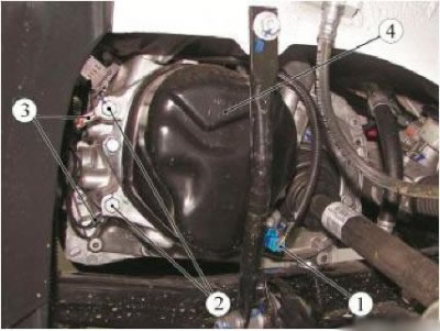
Figure 2-9 - Disconnecting the harness and wire connector "masses" from gearbox: 1 - block of the wiring harness to the reverse light switch; 2 - wire terminal bolt "masses"; 3 - wire "masses"; 4 - gearbox
Unscrew two bolts 2 fastening wire terminals 3 "masses" to the 4 gear box and disconnect the wires "masses" (interchangeable head 13, extension, ratchet wrench).
Loosen the two bolts securing the power steering pipe (in the presence of) to the gearbox and gearbox support and remove the bolts (interchangeable head 13, ratchet knob).
Disconnect the right front wheel drive shaft from the gearbox.
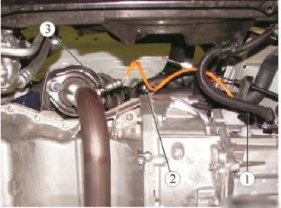
Figure 2-10 - Disconnecting the wiring harness from the control oxygen sensor of the K7M engine: 1 - block of the wiring harness of the control oxygen sensor; 2 - clamp; 3 - control oxygen sensor
Disconnect connector 1, Figure 2-10, control oxygen sensor harness.
Disconnect clamp 2.
Disconnect the harness connector from connector 1, Figure 2-11, diagnostic oxygen sensor.
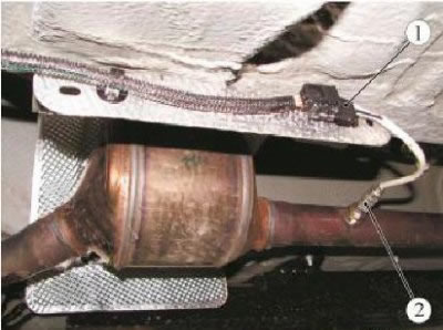
Figure 2-11 - Removing the diagnostic oxygen sensor: 1 - block diagnostic oxygen sensor; 2 - diagnostic oxygen sensor
Disconnect the diagnostic oxygen sensor block from the mounting bracket.
Remove catalytic converter.
For vehicles with K4M engine
Unscrew the four bolts securing the heat shield of the steering mechanism and remove the heat shield (interchangeable head 13, ratchet wrench).
Operations for all vehicle configurations
Loosen the bolts securing the steering gear to the subframe (interchangeable head 18, ratchet wrench).
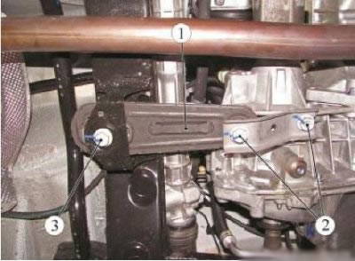
Figure 2-12 - Removing the rear engine mount: 1 - rear engine mount; 2 - a bolt of fastening of a back support of an engine suspension bracket to a transmission; 3 - a bolt of fastening of a back support of an engine suspension bracket to a subframe of a forward suspension bracket
Hang the steering gear to the car body (technological hooks).
Remove rear support 1, Figure 2-12, engine mounts.
Remove the front suspension subframe.
Remove starter 1, Figure 2-13.

Figure 2-13 - Removing the starter: 1 - starter; 2 - nut for fastening the bracket to the intake manifold; 3 - intake manifold; 4 - bracket for fastening the intake manifold to the cylinder block; 5 - cylinder block; 6 - a bolt of fastening of an arm to the block of cylinders
Mount the crosshead 1 on the vehicle, Figure 2-14, for hanging the engine and hang the engine by the lifting eye 2 on the flywheel side (traverse for hanging the engine type RST-500 f. "RANGER").
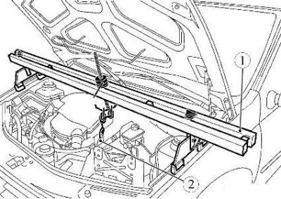
Figure 2-14 - Mounting the crosshead for hanging the engine: 1 - traverse for hanging the engine; 2 - lifting eye
Unscrew nut 1, Figure 2-15, studs securing the gearbox to the cushion 2 of the left engine mount (interchangeable head 16, extension, crank).
Unscrew three bolts 3 fastening the bracket 4 of the left support of the engine mount to the gearbox 5 gears (interchangeable head 16, extension, crank).
Remove the left engine mount bracket from the transmission.
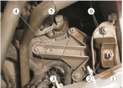
Figure 2-15 - Disconnecting the gearbox from the left engine mount: 1 - a nut of a hairpin of fastening of a transmission; 2 - pillow of the left support of the engine mount; 3 - bolt for fastening the bracket of the left engine mount to the gearbox; 4 - bracket for the left engine mount; 5 - gearbox; 6 - transmission stud
Unscrew three bolts 1, Figure 2-16, upper fastening of gearbox 2 to the engine (interchangeable head 13, extension, crank).
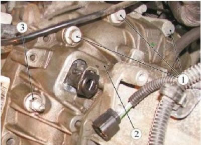
Figure 2-16 - Top mounting of the gearbox to the engine: 1 - a bolt of the top fastening of a transmission to the engine; 2 - gearbox; 3 - nut of a hairpin of fastening of a transmission to the engine
Raise the vehicle to a height that is comfortable for the job.
Install the hydraulic transmission strut under the vehicle and bring its supporting part up to the stop against the gearbox (hydraulic transmission rack type SG-1 "GARO").
Unscrew the four bolts 1, Figure 2-17, lower fastening 2 of the gearbox to the engine (interchangeable head 13, extension, ratchet knob).
Unscrew two nuts 3, Figure 2-16, studs securing the gearbox to the engine (interchangeable head 13, extension, ratchet knob).
Disconnect the gearbox from the engine, lower the base of the hydraulic transmission strut with the gearbox and remove the transmission strut from under the vehicle (hydraulic transmission rack type SG-1 "GARO").
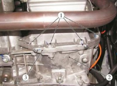
Figure 2-17 - Bottom mounting of the gearbox to the engine: 1 - a bolt of the top fastening of a transmission to the engine; 2 - gearbox; 3 - nut of a hairpin of fastening of a transmission to the engine
Attention! When removing and installing the gearbox, do not rest the end of the input shaft on the petals of the clutch pressure spring to prevent their deformation or breakage.
Preparing for installation
Check the absence of leakage through the input shaft seal, if necessary, replace the guide tube.
Replace the gearbox differential flange seals.
Replace clutch release bearing.
Installation
Before installing the gearbox, make sure that the mounting bushings are present and correctly positioned to ensure centering of the engine and gearbox relative to each other.
For vehicles with JH3 gearbox
Lubricate the sliding surface of the clutch release bearing on the guide bush and the sliding surfaces of the release fork with MOLYKOTE BR2 grease (consumption rate 2 g).
Insert the fork under the paws on the clutch release bearing.
For vehicles with JR5 gearbox
Attention! Do not apply grease to the input shaft of the gearbox to prevent failure of the clutch slave cylinder.
Operations for all vehicle configurations
If necessary, center the clutch disc (mandrel for centering clutch disc Emb. 1518 or Emb. 1780 or 67.7823-9702L).
Install the gearbox on the hydraulic transmission rack and drive under the car (hydraulic transmission rack type SG-1 "GARO").
Raise the gearbox with a hydraulic lift, insert the gearbox input shaft into the splines of the driven disc and screw in the two nuts of the gearbox-to-engine stud bolts. The moment of an inhaling of nuts of hairpins of fastening of a transmission of 44 Nm (4.4 kgf·m) (interchangeable head 13, extension, ratchet knob, torque wrench).
Install four bolts 1, Figure 2-17, lower gearbox to engine (interchangeable head 13, extension, ratchet wrench).
Install the three bolts 1, Figure 2-16, upper mounting of the gearbox to the engine (interchangeable head 13, extension, ratchet wrench).
Tighten the bolts securing the gearbox to the engine with a torque of 44 Nm (4.4 kgf·m) (interchangeable head 13, extension, torque wrench).
Lower the base of the hydraulic transmission strut and remove the transmission strut from under the vehicle (hydraulic transmission rack type SG-1 "GARO").
Install the bracket 4, Figure 2-15, of the left engine mount on the gearbox and secure with three bolts 3. Tightening torque of the bolts of the left mount bracket to the gearbox 62 Nm (6.2 kgf·m) (interchangeable head 16, extension, ratchet wrench, torque wrench).
Install the nut 1 of the stud of the left support on the cushion 2, while the tightening torque of the nut of the stud of the fastening is 62 Nm (6.2 kgf·m) (interchangeable head 16, extension, ratchet wrench, torque wrench).
Install starter 1, Figure 2-13.
For vehicles with K4M engine
Install steering gear heat shield and secure with four heat shield mounting bolts. Tightening torque for steering heat shield mounting bolts 21 Nm (2.1 kgf·m) (interchangeable head 13, ratchet wrench, torque wrench).
Operations for all vehicle configurations
Install the front suspension subframe.
Install rear support 1, Figure 2-12, engine mounts.
Install steering gear.
Connect terminal 1, Figure 2-4, of the wiring harness to the speed sensor.
For vehicles with K7M engine
Install catalytic converter.
Connect the connector 1, Figure 2-11, of the 2 diagnostic oxygen sensor to the wiring harness connector and install the connector on the bracket.
Attach connector 1, Figure 2-10, to control oxygen sensor harness 3 and install connector in holder.
Operations for all vehicle configurations
Install the right front wheel drive shaft.
For vehicles with K4M engine
Install the power steering pipe bolts to the transmission support and to the transmission. Bolt tightening torque 21 Nm (2.1 kgf·m) (interchangeable head 13, ratchet knob, torque wrench).
Operations for all vehicle configurations
Install two terminals 3, Figure 2-9, wires "masses" and two bolts 2 fastenings. Tightening torque of mounting bolts 21 Nm (2.1 kgf·m) (interchangeable head 13, ratchet knob, torque wrench).
Connect connector 1 of the wiring harness to the reverse light switch.
Install the left front wheel drive shaft.
Install the bottom and side mudguards.
Install the three bolts securing the front bumper to the subframe (replaceable nozzle Torx T30, extension, knob).
Replace the gasket on the transmission drain plug.
Screw in the drain plug in the gearbox housing and tighten to 22 Nm (2.2 kgf·m) (key for inner square 1/2", torque wrench).
Unscrew the filler plug, pour oil into the gearbox and tighten the plug. The oil level should be at the bottom edge of the filler hole (filling station for gear oils type C-223-1, gear oil according to the current "Codifier of the main and auxiliary materials used in the maintenance and repair of LADA vehicles" K 3100.25100.00018, oil consumption rate: for JH3 gearbox - 2.8 l; for gearbox JR5 - 2.5 l).
Install the engine undertray.
Remove traverse 1 from the vehicle, Figure 2-14, for hanging the engine (traverse for hanging the engine type RST-500 f. "RANGER").
For vehicles with JR5 gearbox
Connect the pipeline 1, Figure 2-6, of the clutch hydraulic actuator to the clutch slave cylinder 2.
Bleed the air from the hydraulic clutch.
Install stoppers 3, Figure 2-5, of the sheaths of the select and shift cables into the gearbox brackets.
Connect the hinges 1 of the select and shift cables to the levers 2 of the gearbox.
For vehicles with JH3 gearbox
Attach cable 1, Figure 2-8, of the clutch actuator to the gearbox.
Check clutch adjustment.
Install rod 3, Figure 2-7, of the gearbox control drive and fasten the rod fastening bolt 2. The moment of an inhaling of a bolt of fastening of draft of a drive of a gear change 28 Nm (2.8 kgf·m) (interchangeable head 10, extension, knob, torque wrench).
Install protective cover 1 for gear lever.
Operations for all vehicle configurations
Install front wheels.
Install the expansion tank 2, Figure 2-3, onto the bracket. Tightening torque of nuts 1 of fastening of expansion tank 8 Nm (0.8 kgf·m) (interchangeable head 10, ratchet wrench, torque wrench).
Install the wiring harness bracket and wiring harness to the transmission.
Install the ECM.
Install the battery tray.
Install the battery.
For vehicles with K4M engine
Install the intake silencer.
Operations for all vehicle configurations
Check and, if necessary, adjust the alignment of the front wheels.