



See catalog numbers. here and here.
The starter is mounted on the clutch housing at the rear of the engine.
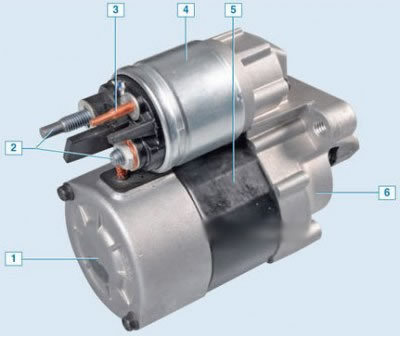
VALEO starter: 1 – back cover; 2 – contact bolts; 3 – control output of the traction relay; 4 – traction relay; 5 – starter housing; 6 – front cover
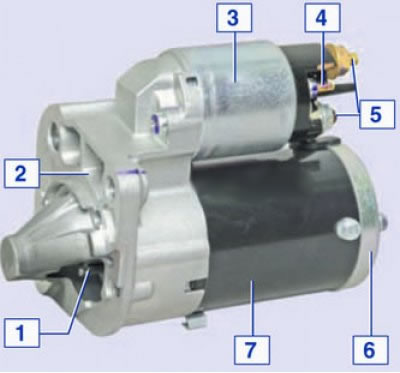
MITSUBISHI starter: 1 – drive gear; 2 – front cover; 3 – traction relay; 4 – control output of the traction relay; 5 – contact bolts; 6 – back cover; 7 – body
Useful tips. In order to avoid many starter malfunctions, follow a number of simple rules when operating it:
- when starting the engine, turn on the starter for no more than 10-15 seconds and again after 20-30 seconds. Continuous long-term operation of the starter can lead to overheating. If after three attempts the engine does not start, then the faults in the engine power supply system or in the ignition system should be checked and corrected;
- after starting the engine, immediately turn off the starter, as prolonged rotation of the flywheel drive gear may damage the starter overrunning clutch;
- it is not allowed to move the car using the starter, as this causes its significant overload and damage.
Removal
Place the vehicle on a two-post lift (electro-hydraulic lift type P-3.2 G with a lifting capacity of 3.2 t). Apply the parking brake.
Turn off the ignition, raise the hood, disconnect the ground wire terminal from the battery (10 mm spanner).
Remove the casing (if available) electronic control unit ECU, pressing two clamps (flat head screwdriver).
Unscrew the two nuts 1, Figure 3-1, securing the expansion tank 2 (10 mm spanner).
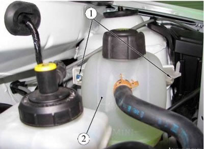
Figure 3-1 - Expansion tank mounting: 1 - expansion tank mounting nut; 2 - expansion tank
Remove and set aside the expansion tank without disconnecting the hoses.
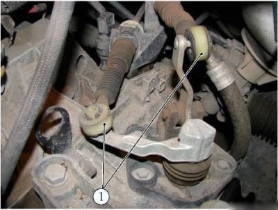
Figure 3-2 - Disconnecting the gear selector and shift cables: 1 - gear selection and shift cable hinges
For vehicles equipped with JR 5 gearbox:
- disconnect the joints 1, figure 3-2, of the gear selection and shift cables from the gearbox (flat head screwdriver);
- press the clamps on both sides and disconnect the locking clips of the gear selection and shift cable housings from the gearbox bracket.
For vehicles equipped with the JH3 gearbox:
- remove cover 1, figure 3-3, of the gear shift drive rod hinge;
- unscrew bolt 2 securing the gear shift drive rod, remove the spacer sleeve and disconnect the rod (10 mm spanner).
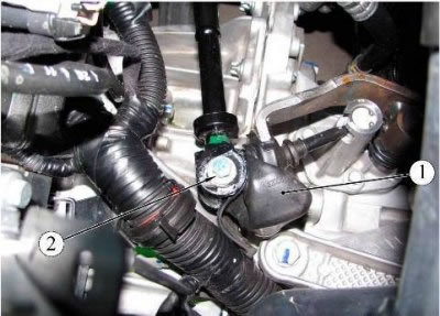
Figure 3-3- Disconnecting the gear shift rod: 1 - case; 2 - gear shift drive rod mounting bolt
Unscrew the three bolts 1, Figure 3-4, securing the starter (replacement head 13, ratchet handle, extension).
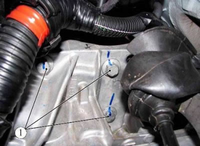
Figure 3-4 - Starter mount: 1 - starter mounting bolt
Raise the vehicle to a height convenient for performing the work.
Unscrew nut 2, Figure 3-5, securing bracket 4 to intake manifold 3 (replacement head 13, ratchet handle, extension).
Loosen bolt 6 securing bracket 4 to cylinder block 5 (replacement head 17, ratchet handle, extension).
Remove bracket 4 securing intake manifold 3.
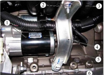
Figure 3-5 - Removing the starter: 1 - starter; 2 - nut securing the bracket to the intake manifold; 3 - intake manifold; 4 - bracket for fastening the intake manifold to the cylinder block; 5 - cylinder block; 6 - bracket mounting bolt to cylinder block
Loosen nut 2, Figure 3-7, and disconnect harness 1, Figure 3-6, of ignition system wires from starter 3 (replacement head 10, ratchet handle, extension).
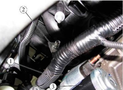
Figure 3-6 - Fastening the ignition system wiring harness: 1 - ignition system wiring harness; 2 - wiring harness mounting bracket; 3 - starter
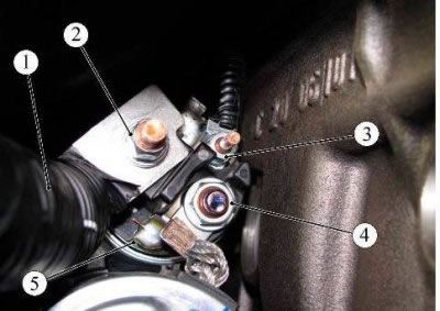
Figure 3-7 - Disconnecting the wiring harness from the starter: 1 - wiring harness; 2 - nut of the bracket for fastening the wiring harness to the starter; 3 - starter electromagnetic relay wire fastening nut; 4 - starter wire fastening nut; 5 - starter
Unscrew nut 4, figure 3-7, fastening starter wire 5 (replacement head, ratchet handle, extension).
Disconnect the starter wire.
Unscrew nut 3 securing the starter electromagnetic relay wire 5 (replaceable head 8, ratchet handle, extension).
Remove the starter.
Lower the car.
Installation
Install the starter in the reverse order of removal.
In this case, the tightening torques of threaded connections are:
- starter mounting bolt - 44 Nm (4.4 kgf·m);
- starter wire fastening nut - 8 N·m (0.8 kgf·m);
- starter electromagnetic relay wire fastening nut - 5 Nm (0.5 kgf·m);
- gear shift drive rod mounting bolt - 27.5 Nm (2.75 kgf·m).
Connect the terminals to the battery.