



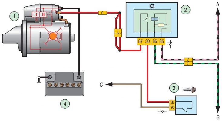
Figure 10.3. Starter connection diagram: 1 – starter; 2 – mounting block; 3 – ignition switch (lock); 4 – battery; A – to the main relay, terminal "30"; B – to contact "50" of the ECU; C – to the main fuse box (F3); K3 – starter relay
The starter connection diagram is shown in the figure 10.3.
Technical characteristics of the starter mod. 2111.3708010–01
Nominal voltage, V — 12
Nominal power, kW — 1.2
Current consumption, A:
- at maximum power - 375
- in a inhibited state, no more than - 700
- at idle - 80
Current consumption of traction relay, A:
Article copied from this portal: Ladaman.ru
- pull-in winding - 43
- holding winding - 12
Drive gear:
- number of teeth - 9
- module, mm — 2.116
- angle of the original contour, degrees - 12
The starter 2111.3708010-01 with excitation from permanent magnets is a direct current electric motor with an electromagnetic two-winding traction relay and a freewheel clutch. The starter is designed for use in moderate and tropical climates.
The starter operating mode is short-term, lasting up to 10 s. At negative temperatures, the operating time is allowed to be up to 15 s. The starter is powered by a 55 A h battery. It is a recoverable, serviceable product.
Note: To avoid many starter malfunctions, follow a number of simple rules when operating it:
- when starting the engine, turn on the starter for no more than 10-15 seconds and again after 20-30 seconds. Continuous long-term operation of the starter can lead to overheating. If after three attempts the engine does not start, then the faults in the engine power supply system or in the ignition system should be checked and corrected;
- after starting the engine, immediately turn off the starter, as prolonged rotation of the flywheel drive gear may damage the starter overrunning clutch;
- it is not allowed to move the car using the starter, as this causes its significant overload and damage.