



Mod generator. 5102.3771 has a number of advantages over earlier domestically produced analogues. The most significant difference is the increased current output of the generator at low engine speeds (the increase is 4–6 A with a decrease in generator rotor speed by 300 min⁻¹), which is especially necessary when operating the car in winter, and will also allow the use of an automatic transmission in the car design in the future.
Technical characteristics of the generator 5102.3771
- Maximum output current at 14 V, A - 80
- Adjustable voltage, V — 13.8–14.4
- Engine-generator gear ratio: 1:2.4
- Specific power, W/kg — 205
- Weight, kg — 5.4
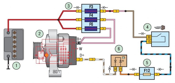
Figure 10.1. Generator connection diagram: 1 – battery; 2 – generator; 3 – main fuse box; 4 – ignition switch (lock); 5 – mounting block; 6 – Low battery indicator light
The generator connection diagram is shown in the figure 10.1. The voltage for exciting the generator when the ignition is turned on is supplied to the "D+" terminal of the regulator through the 6th battery discharge indicator lamp located in the instrument cluster.
After starting the engine, the excitation winding is powered by three additional diodes installed on the generator rectifier block.
The "W" terminal of the generator is not used on Lada Priora cars.
The operation of the generator is monitored using the low battery indicator light located in the instrument cluster. When the ignition is turned on, the lamp should light up, and after the engine starts, it should go out if the generator is working properly. A brightly lit lamp or one that burns at half brightness indicates a malfunction.
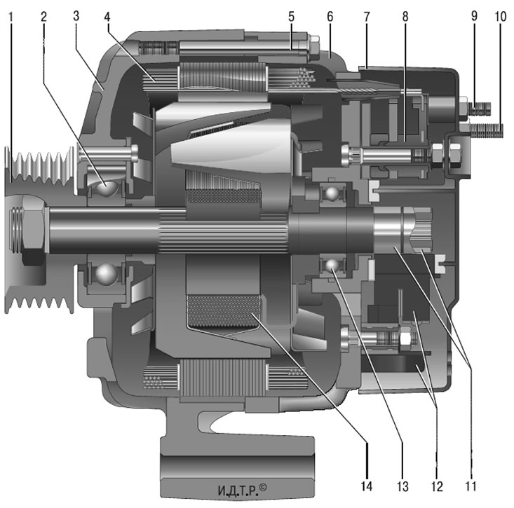
Figure 10.2. Generator 5102.3771: 1 – pulley; 2 – front bearing; 3 – front cover; 4 – stator; 5 – tension bolt; 6 – back cover; 7 – casing; 8 – rectifier block; 9 – output "D+" of the generator; 10 – generator output "B+"; 11 – rotor slip rings; 12 – voltage regulator with brush holder; 13 – rear rotor shaft bearing; 14 – rotor
Stator 4 (figure 10.2) and covers 3 and 6 are pulled together with four screws. Rotor shaft 14 rotates in bearings 2 and 13, which are installed in the covers. Power supply to the rotor winding (excitation winding) is supplied through brushes and contact rings 11.
Three-phase alternating current induced in the stator winding is converted into direct current by the rectifier unit 8, attached to the cover 6. The electronic voltage regulator 12 is combined into one unit with the brush holder and is also attached to the cover 6.