



1. Remove the generator from the vehicle (see "Removing and installing the generator").
2. Remove the voltage regulator (see "Checking and replacing the voltage regulator with brush holder").
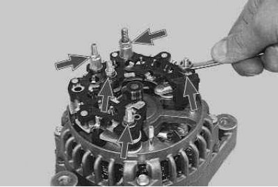
3. Unscrew the three nuts securing the rectifier unit and the two nuts securing the spacer bushings of the positive terminal and the generator excitation terminal...
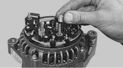
4. ...then remove the bushings.
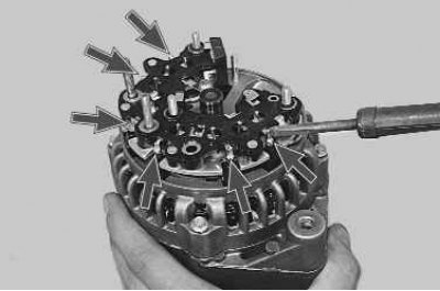
5. Unsolder the six terminals of the stator winding...
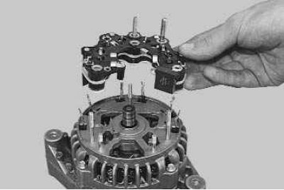
6. ...and remove the rectifier block from the generator.
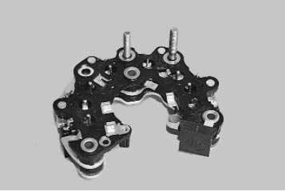
Note: This is what the removed rectifier unit looks like from the side of the protective casing...
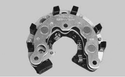
...and so - from the stator side.
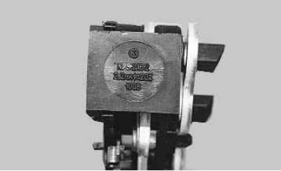
This is what a capacitor looks like, which is non-removable.
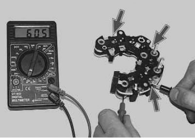
7. Check the "negative" diodes by connecting the "positive" (red) probe of the tester to the "minus" plate (bus) of the rectifier unit, and the "negative" (black) probe alternately to the three contact terminals of the diodes in three places (every other one) fastening of stator windings. If the diodes are good, the tester will show 580–620 Ohms.

8. Connect the "negative" (black) probe of the tester to the "minus" plate of the rectifier unit, and the "positive" (red) probe in turn to the same three contact terminals. If the diodes are good, the tester will show infinite resistance.
9. If the tester shows low or close to zero resistance, then the diode is "broken", if the tester reading tends to infinitely high resistance regardless of the color of the connected probes, then the diode is "open". In both cases, the rectifier unit must be replaced.
10. Similarly, check the "positive" diodes, but only relative to the "positive" plate of the rectifier block or the "B+" terminal of the generator.
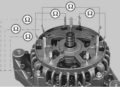
11. Check the stator windings for breaks using a tester (solid line diagram) and for the absence of a short circuit to the starter housing (dotted line diagram). When taking measurements, ensure that the winding terminals do not touch the generator cover.
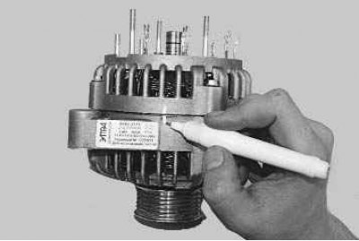
12. Mark the relative positions of the generator covers...
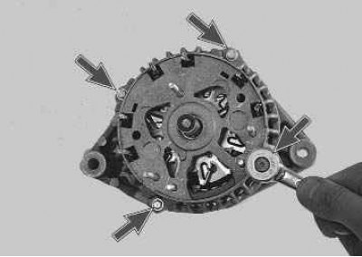
13. ...unscrew the four tie bolts...
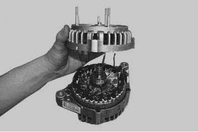
14. ...and, using a screwdriver, remove the generator cover from the contact ring side.
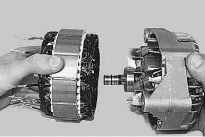
15. Remove the stator from the cover.
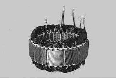
16. Inspect the stator. There should be no traces of the anchor touching the stator on its inner surface. If there is wear, the bearings or generator covers need to be replaced.
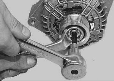
17. Place the open-end wrench on the nut and insert the Allen key through its hole into the shaft hole. Use a spanner to loosen the nut while holding the shaft from turning.
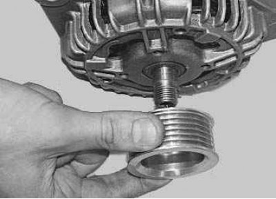
18. Remove the spring washer and pulley from the rotor shaft.
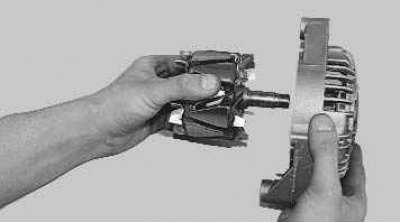
19. Remove the rotor shaft from the bearing. If necessary, screw the pulley mounting nut onto the rotor shaft and, using a wooden spacer, lightly tap the rotor shaft out of the bearing with a hammer.
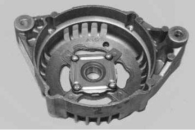
20. Inspect the drive side cover (complete with generator bearing).
21. If, when rotating the bearing, you feel play between the rings, rolling or jamming of the rolling elements, the protective rings are damaged or there are grease leaks, replace the bearing, and if cracks are found in the cover, especially in the places where the generator is attached, it is necessary to replace the generator cover.
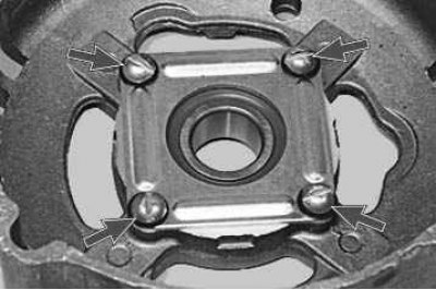
22. To replace the bearing or cover, remove the four screws securing the bearing thrust washer...
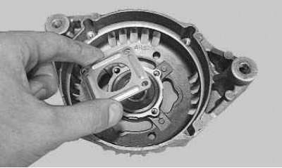
23. ...and remove the washer.
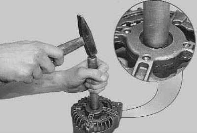
24. Using an aluminum spacer, lightly tap the bearing out of the generator cover with a hammer.
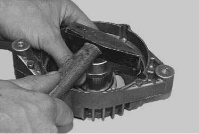
25. Press the new bearing into the cover using a socket head of the appropriate diameter.
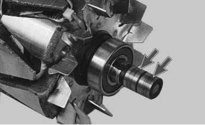
26. Inspect the contact rings. If they have burrs, scratches, marks from brushes and other defects, the rings must be ground. If the damage to the rings cannot be removed with sandpaper, turn the rings on a lathe, removing a minimal layer of metal, and then grind.
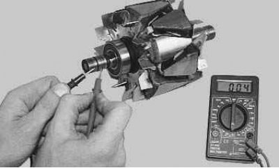
27. Check the rotor winding resistance with a tester by connecting it to the slip rings. If the tester shows infinity, it means there is a break in the rotor winding and it needs to be replaced.
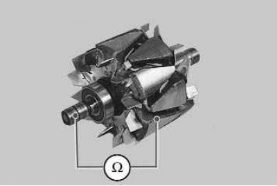
28. Check for a short circuit between the rotor winding and the housing by connecting the tester leads to any contact ring and the rotor housing. The tester should show infinity.
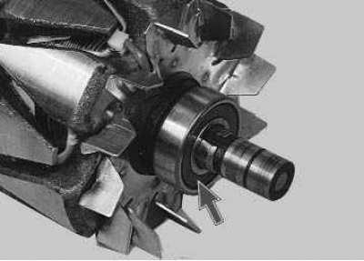
29. Check the ease of rotation of the bearing from the contact ring side. If, when rotating the bearing, there is play between the rings, rolling or jamming of the rolling elements, damaged protective rings or grease leaks, the bearing must be replaced.
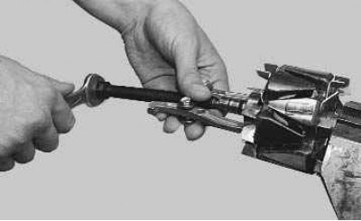
30. To do this, use a puller to press the bearing off the rotor shaft and press on a new one using a suitable mandrel, applying force to the inner ring of the bearing.
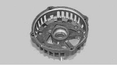
31. Inspect the generator cover from the contact ring side. If cracks are found, the cover must be replaced.
Note: Replace all parts in specialized workshops or at an authorized dealer, since the cost of spare parts is quite high, and replacing parts is labor-intensive, using professional tools. Moreover, in these cases, qualified diagnostics are required. After repairs, the generator must be tested on a diagnostic stand. This stand simulates the actual operation of a generator with variable loads, while at the same time continuously monitoring the voltage and charging current. Based on the obtained inspection results, the contractor provides a guarantee both for the spare parts purchased and installed by him, and for the repair and diagnostic work performed.
32. Assemble the generator in the reverse order of disassembly, orienting the generator covers and stator housing according to the marks made earlier.