



- Maximum output current (at 14 V and 6000 min⁻¹), A — 120
- Engine-generator gear ratio: 2.4
Generator type TG 12C209 f. "Valeo" alternating current, three-phase, with built-in rectifier unit and voltage regulator, right rotation (from the drive side), designed to operate as a source of electrical energy in parallel with the battery in the electrical system of a vehicle, designed for operation at an ambient temperature of - 40 to +45 0C and humidity up to 90% at a temperature of +27 0C.
Removal
For cars of all trim levels
Place the vehicle in the work area and apply the parking brake.
Turn off the ignition, lift the hood, disconnect the ground wire terminal from the battery (spanner 10).
Remove the right front wheel in accordance with the requirements of TI 3100.25100.20594.
Raise the vehicle to a height convenient for performing the work.
[Material was taken from the website LadaMan.ru]
Remove the mudguard of the right front wing in accordance with the requirements of TI 3100.25100.20599.
Remove the engine mudguard in accordance with the requirements of TI 3100.25100.20594.
Remove belt 5, Figure 4-1, of the attachment drive in accordance with the requirements of TI 3100.25100.20592.
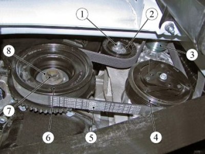
Figure 4-1 - Drive belt for auxiliary units on vehicles with air conditioning system: 1 - tension roller fastening nut; 2 - tension roller; 3 - generator pulley; 4 - air conditioning compressor pulley; 5 - drive belt for attachments; 6 - crankshaft damper; 7 - damper mounting bolt; 8 - washer
For cars with engines 21129 and 21179 with air conditioning system
Unscrew the three bolts 1, Figure 4-2, fastening, remove the compressor 2 of the air conditioning system without breaking the tightness of the system, and hang it on a technological hook (replaceable head 10, ratchet, technological hook).
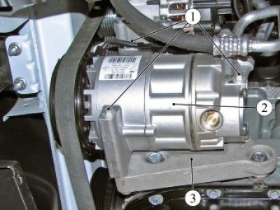
Figure 4-2 - Removing the air conditioning compressor: 1 - bolt; 2 - air conditioning compressor; 3 - bracket for mounted units
For cars of all trim levels
Remove the protective cap, unscrew the nut 1, Figure 4-3, fastening and disconnect terminal 2 of the wiring harness from the generator 5 (replacement head 13, extension, ratchet).
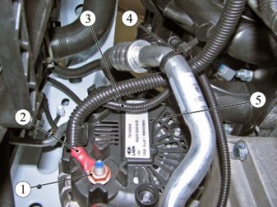
Figure 4-3 - Connecting the wiring harnesses to the generator: 1 - nut; 2 - terminal of the wiring harness to the generator; 3 - wiring harness; 4 - clamp; 5 - generator
Disconnect the 3-wire harness connector from the generator.
Unscrew the four bolts 1, Figure 4-4, fastenings and remove the generator 2 (replacement head 10, ratchet).
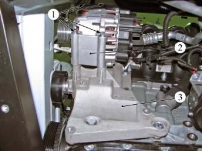
Figure 4-4 - Generator mounting: 1 - bolt; 2 - generator; 3 - bracket for mounted units
Installation
For cars of all trim levels
Install generator 2, Figure 4-4, on bracket 3 of the mounted units and secure with four bolts 1. Tightening torque of generator mounting bolts 21...27 N·m (2.1...2.7 kgf·m) (replaceable head 10, ratchet, torque wrench).
Connect the harness block 3, Figure 4-3, of the wires to the generator.
Connect terminal 2 of the wiring harness to generator 5 and tighten fastening nut 1. Tightening torque of the terminal fastening nut 18...24 N·m (1.8...2.4 kgf·m) (replaceable head 13, extension, ratchet, torque wrench).
Place the protective cap on the terminal mounting nut.
For cars with engines 21129 and 21179 with air conditioning system
Install compressor 2, Figure 4-2, of the air conditioning system on the bracket of the mounted units and secure with three bolts 1. Tightening torque of the compressor mounting bolts 21...27 N·m (2.1...2.7 kgf·m) (replaceable head 10, ratchet, torque wrench).
For cars of all trim levels
Install belt 5, Figure 4-1, of the drive of attachment units in accordance with the requirements of TI 3100.25100.20592.
Install the engine mudguard in accordance with the requirements of TI 3100.25100.20594.
Install the mudguard of the right front wing in accordance with the requirements of TI 3100.25100.20599.
Install the right front wheel in accordance with the requirements of TI 3100.25100.20594.
Present the vehicle to the Quality Control Department. The Quality Control Department will check the generator operation for compliance with the requirements of this TI and the requirements of TU 017200-254-00232934, paragraphs 1.19.21.3, 1.19.21.6, 2.3.