



Radio receiver and audio player, multimedia navigation equipment
The car is equipped with a radio receiver and audio player or multimedia navigation equipment. The operations for removing these radio devices from the vehicle and installing them on the vehicle are identical.
Removal
Place the vehicle in the work area, apply the parking brake, and turn off the ignition. Raise the hood, disconnect the ground wire terminal from the battery (spanner 10).
Disconnect the central trim 1, Figure 19-1, from the instrument panel 2, overcoming the resistance of the clips.
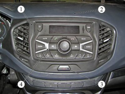
Figure 19-1 - Removing the instrument panel center trim: 1 - central instrument panel trim; 2 - instrument panel; 3 - emergency signaling button; 4 - radio receiver and audio player
Disconnect the instrument panel wiring harness connector from the connector of the hazard warning light button 3 installed on the center trim panel and remove the center trim panel.
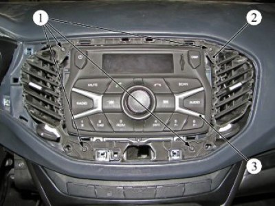
Figure 19-2 - Removing the central body ventilation nozzle: 1 - self-tapping screw; 2 - central body ventilation nozzle; 3 - radio receiver and audio player
Unscrew four screws 1, Figure 19-2, self-tapping and remove the central nozzle 2 of the body ventilation (t20 bit, screwdriver).
Unscrew the four screws 1, Figure 19-3, self-tapping and remove the radio receiver and audio file player 2 from the socket in the instrument panel 3 (t20 bit, screwdriver).
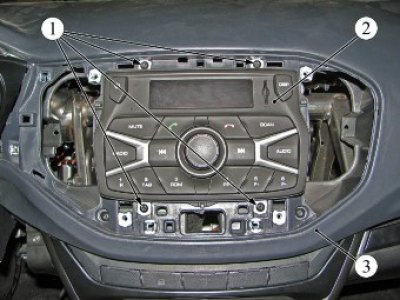
Figure 19-3 - Removing the radio and audio player: 1 - self-tapping screw; 2 - radio receiver and audio player; 3 - instrument panel
Disconnect connectors 1 and 2, Figure 19-4, of the instrument panel wiring harness from the radio and audio player connectors 5.
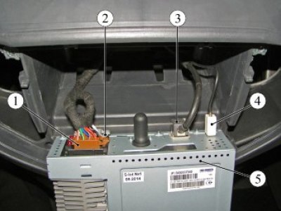
Figure 19-4 - Disconnecting the connectors and wiring harnesses from the radio and audio player: 1, 2 - instrument panel wiring harness connector; 3 - USB cable connector; 4 - antenna cable connector; 5 - radio receiver and audio player
Disconnect connectors 3 of the USB cable and 4 of the antenna cable from the connectors of the radio and audio player.
Disconnect the steering wheel multimedia control unit cable connector (if available) from the radio receiver and audio player connectors.
Remove the radio and audio player.
Installation
Install the radio and audio player in the reverse order of removal.
When installing the radio receiver into the instrument panel socket, check that the wires are routed into the corresponding holes in the instrument panel to prevent them from being pinched.
Antenna with antenna cable assembly
Removal
Remove the lampshade 1, Figure 19-5, of the interior lighting in accordance with the requirements of Section 16 of this technological instruction.
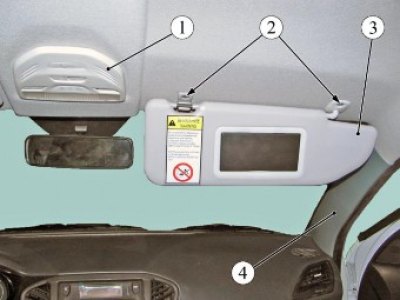
Figure 19-5 - Removing the antenna: 1 - interior lighting lamp; 2 - screw; 3 - right sun visor; 4 - right windscreen pillar trim
Unscrew two screws 2 and remove the right sun visor 3 (t20 bit, screwdriver).
Remove the trim of the 4th pillar of the right windshield, overcoming the resistance of the holders (flat head screwdriver).
Disconnect connectors 1 and 2, Figure 19-6, of the antenna cable from the connectors of harness 5 of the instrument panel.
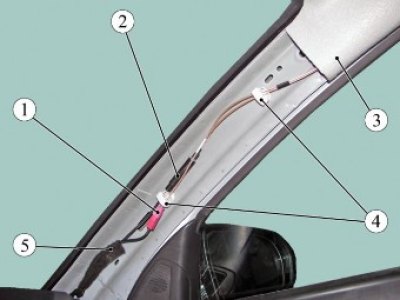
Figure 19-6 - Antenna cable fastening elements: 1 - navigation system antenna cable connector; 2 - radio antenna cable connector; 3 - roof lining; 4 - antenna cable fastening element; 5 - Instrument cluster wiring harness
Remove the antenna cable from the two 4 fastening elements on the right windshield pillar. Remove two plugs 1, Figure 19-7, of the right front handrail (flat head screwdriver). Unscrew two screws 2 and remove the right front handrail 3 (t20 bit, screwdriver).
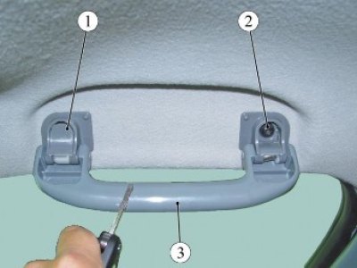
Figure 19-7 - Fastening the right front handrail: 1 - plug; 2 - screw; 3 - right front handrail
Unscrew nut 1, figure 19-8, fastening the antenna to the roof panel, remove washer 2 (replacement head 22, extension, ratchet).
Material was taken from the website: LadaMan.ru
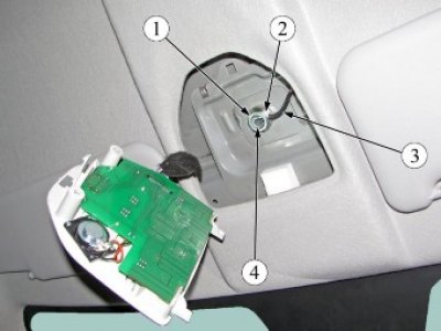
Figure 19-8 - Antenna mounting elements: 1 - antenna mounting nut; 2 - washer; 3 - antenna cable; 4 - antenna
Carefully fold back the right front part of the roof lining, avoiding bending the lining. Disconnect the two clamps securing the antenna cable to the body (flat head screwdriver).
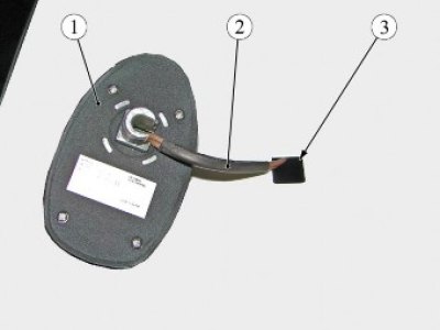
Figure 19-9 - Antenna mounting elements (view from the roof): 1 - antenna; 2 - antenna cable; 3 - holes in the roof panel for installing the antenna
Remove antenna 1, Figure 19-9, from opening 3 in the roof panel together with antenna cable 2.
Installation
Install the antenna with the antenna cable assembly in the reverse order of removal.
Loudspeakers
Removal and installation of front and rear speakers shall be carried out in accordance with the requirements of the sections on disassembly and assembly of the front and rear doors, respectively, TI 3100.25100.20589.
Present the vehicle to the Quality Control Department. The Quality Control Department will check the vehicle for compliance with the requirements of TU 017200-254-00232934-2006, paragraphs 1.19.21.3, 1.19.21.6 in the scope of work performed.