



Removal
Place the vehicle in the work area, apply the parking brake, and turn off the ignition. Raise the hood, disconnect the ground wire terminal from the battery (spanner 10).
Overcoming the resistance of the clamps, remove the trim 1, Figure 6-1, of the instrument panel console on the driver's side (flat head screwdriver).
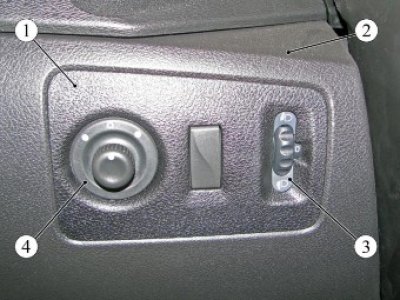
Figure 6-1 - Headlight range control switch: 1 - dashboard console trim on the driver's side; 2 - instrument panel; 3 - headlight corrector switch; 4 - electric mirror adjustment handle
Disconnect connector 1, Figure 6-2, of the instrument panel wiring harness from switch 2 of the headlight beam corrector.
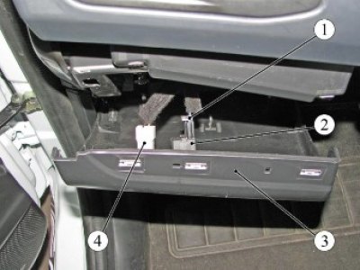
Figure 6-2 - Instrument cluster wiring harness connectors: 1 - connector of the instrument panel wiring harness to the headlight corrector switch; 2 - headlight corrector switch; 3 - fuse box cover; 4 - connector of the instrument panel wiring harness to the trunk lock switch
Disconnect connector 4 of the instrument panel wire harness from handle 4 of the electric mirror adjustment.
Press the latches and remove switch 1, Figure 6-3, of the headlight beam corrector from cover 2 of the fuse box.
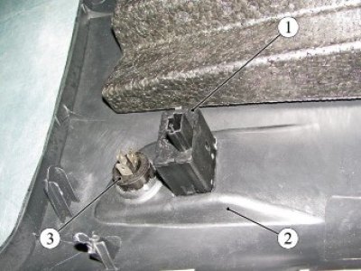
Figure 6-3 - Removing the headlight range control switch and trunk lock switch: 1 - headlight corrector switch; 2 - fuse box cover; 3 - electric mirror adjustment handle
Press the latches and remove the electric mirror adjustment handle from the trim.
Installation
Install switch 3, Figure 6-1, the electric headlight corrector and the electric mirror adjustment knob 4 in the reverse order of removal.
Present the vehicle to the Quality Control Department. The Quality Control Department will check the vehicle for compliance with the requirements of TU 017200-254-00232934, paragraphs 1.19.21.3, 1.19.21, 2.3.