



For part numbers of this unit, see here.
Generator replacement is described here.
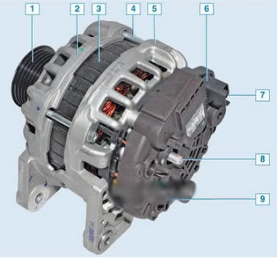
Bosch Generator: 1 – generator pulley; 2 – front cover; 3 – stator; 4 – tension bolt; 5 – back cover; 6 – brush holder with voltage regulator; 7 – brush holder connector; 8 – output "B+"; 9 – casing
the "minus" of the battery should always be connected to the "ground" of the car, and the "plus" to the "B+" terminal of the generator. Reverse connection will cause breakdown of the generator rectifier block diodes.
Brush assembly with voltage regulator (brush holder) is located under the cover (casing) of the generator. The voltage regulator is a non-separable unit; if it fails, it is replaced as a whole with the brush holder. To replace it you need remove generator, remove the generator casing and unscrew the 4 brush assembly screws.

Brush holder with voltage regulator: 1 - contact "mass"; 2 – brush holder body; 3 – voltage regulator; 4 – electrical connector; 5 – contact "B+"; 6 – brushes
Generator malfunctions

The working principle of an alternator
Rotor of an alternator (sometimes called an alternator) is driven by the engine via a belt drive. Due to electromagnetic induction, the rotor's magnetic field excites current in the stator windings (figure 4.20 and 4.21).
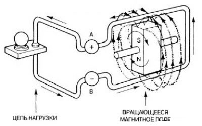
Figure 4.20. The lines of force of a rotating magnetic field, penetrating a closed conducting circuit, excite an electric current in it
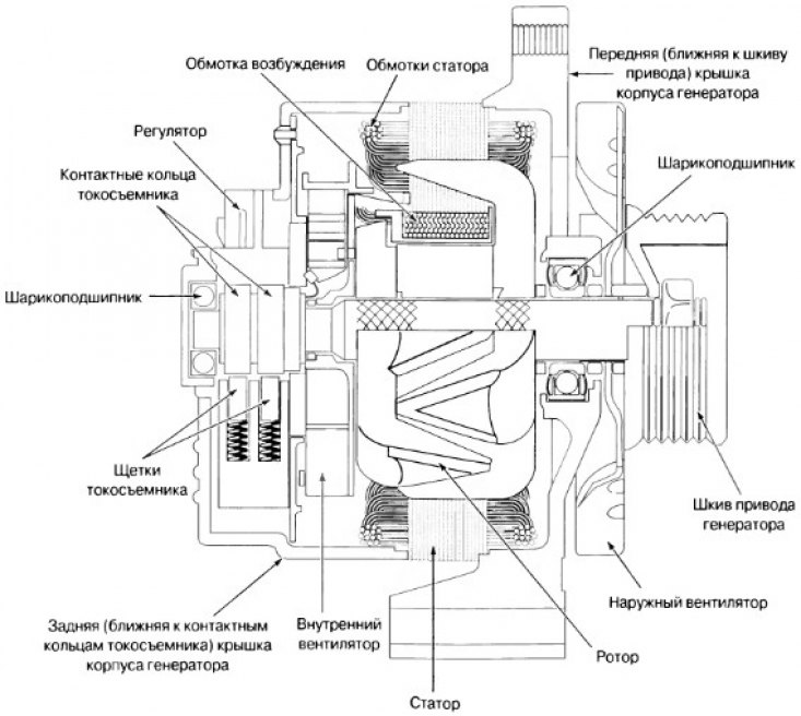
Figure 4.21. Typical alternator design (alternator)
The measurement of the battery charging voltage is performed using the following method
(The material was taken from a website: LadaMan)
1. Connect a voltmeter to the battery, observing polarity.
2. Set the voltmeter to the DC voltage measurement mode.
3. Start the engine and bring its rotation speed to increased idle speed (approximately 2000 rpm).
4. Record the voltmeter reading and compare it with the rated value (figure 4.22). If the measured voltage is lower than the rated voltage, before replacing the generator, charge the battery and check the voltage in the charging circuit again.
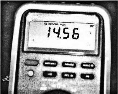
Figure 4.22. The digital multimeter must be set to the DC voltage measurement mode and its red wire must be connected to the positive terminal and the black wire to the negative terminal of the battery
Advice
If the voltmeter readings first increase and then decrease as the engine speed increases, the cause is a loose or slipping alternator drive belt.
Check the fuse for serviceability using a test indicator light.
Most generators have a fused plug connector in the cable that connects the terminal on the rear generator cover closest to the slip rings to the positive terminal of the battery. If this connection is faulty (fuse blows) the battery charging system becomes inoperative. It has happened more than once that the generator was removed and then put back in its place, only because this blown fuse was not noticed in time. A quick and easy way to check if a fuse is working is to touch the indicator light probe, the other end of which is connected to ground, to the generator output terminal. If the light comes on, the fuse is intact. This test ensures that the circuit between the generator and the battery is not broken.
 |
 |
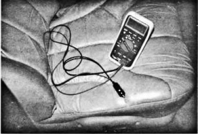
Figure 4.23. A simple and convenient measuring cable can be made from a two-wire cable, a cigarette lighter socket plug, and two single-pole plugs ("bananas") that fit into the COM and V sockets of most digital measuring instruments (a). By connecting the measuring instrument to the cigarette lighter socket with such a cable, you can easily measure the voltage in the charging circuit of the battery (b).
Use the cigarette lighter socket
The battery voltage can be measured through the cigarette lighter socket (figure 4.23). To do this, you need to make a cable adapter. Take a two-wire cable and connect to it on one side a cigarette lighter socket plug, and on the other side - two single-pole plugs with longitudinal spring contacts (the so-called "bananas"). These plugs are suitable! for the COM (common) socket and the voltage measuring socket of most measuring devices.
Monitoring alternating voltage at the generator output
There should be no alternating voltage at the output of a functioning alternator. Rectifier diodes installed in the alternator are required to rectify the alternating voltage produced by the generator, converting it into direct voltage. Control of alternating voltage is performed according to the following method:
Step 1. The digital meter is set to the AC voltage measurement mode.
Step 2. Start the engine and increase its rotation speed to 2000 rpm.
Step 3. Connect the voltmeter to the battery terminals.
Step 4: Turn on the headlights to provide load to the generator.
Note
To obtain more accurate readings, the voltmeter is connected to the generator output terminals.
The measurement results are interpreted as follows: if the rectifier diodes are in good condition, the amplitude of the alternating voltage measured by the voltmeter should be less than 0.4 V. If it exceeds 0.5 V, this means that the rectifier diodes are faulty.
This technique is not suitable for diagnosing faulty diodes.
Checking the power generated by the generator
The electrical supply system may be able to provide the required voltage, but at the same time be unable to provide the required power. If there is any doubt about the power generated by the electrical supply system, the first thing to check is the tension of the alternator drive belt. With the engine off, try to turn the generator fan by hand. If this is successful, replace or adjust the drive belt tension. Figure 4.24 and 4.25 show how the test equipment is connected to check the generator output power.
The generator output power is checked using the following method:
Step 1. Connect the test equipment cables to measure the generator power in starting and charging mode according to the manufacturer's instructions.
Step 2: Turn the ignition key (the engine is not working) and record the ammeter reading. This measurement gives the amount of current consumed by the ignition system - it should be between 2 A and 8 A.
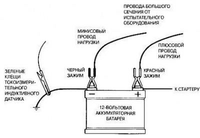
Figure 4.24. Typical connection diagram of test equipment when measuring current in starting and charging mode
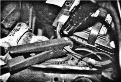
Figure 4.25. The clamp of the current measuring inductive sensor must cover all cables coming from the battery terminal. It doesn't matter what kind of cables they are - positive or negative - because the battery has an equal current flowing into and out of it
Step 3: Start the engine and increase the speed to 2000 rpm (increased idle speed). Slowly rotate the load regulator until the maximum ammeter reading is obtained. Record this reading.
Step 4: Add the ammeter readings obtained in Step 2 and Step 3. The result should not differ by more than 10% (or 15 A) from the generator's rated output current.
If the measured current differs from the rated generator output current by more than 10%, repeat the test with the voltage regulator disconnected and full excitation current applied through the generator rotor excitation winding.
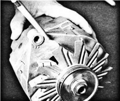
Figure 4.26. The nominal output current of most GM alternators is stamped on the front cover - on its side facing the alternator drive pulley, or on top, under a small boss with a threaded mounting hole
Note
When adjusting the load applied to the battery when testing the generator for output current using a carbon rheostat test equipment, be careful not to allow the battery voltage to drop below 12 V. Most generators produce maximum output current at voltages above 13 V.