
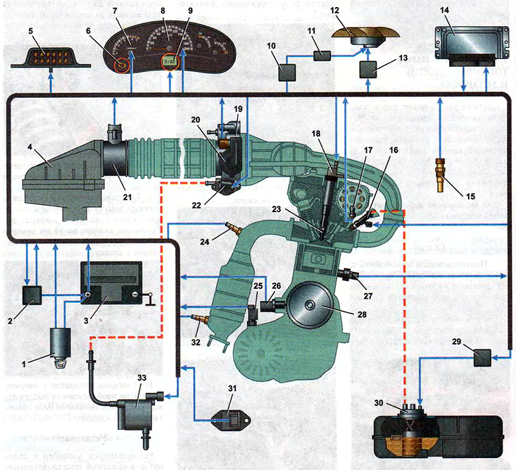
Engine control system diagram:
1 - switch (lock) ignition;
2 - main relay;
3 - battery;
4 - air filter;
5 - block of the diagnostic connector;
6 - control lamp for a malfunction of the engine management system;
7 - tachometer;
8 - speedometer;
9 - trip computer display;
10 - relay for turning on the electric fan (low speed);
11 - additional resistor;
12 - electric fan of the engine cooling system;
13 - relay for turning on the electric fan (high speed);
14 - electronic engine control unit (ECU);
15 - coolant temperature sensor;
16 - nozzles;
17 - camshaft position sensor (phase sensor);
18 - ignition coil;
19 - throttle assembly;
20 - throttle position sensor;
21 - mass air flow sensor;
22 - idle speed regulator;
23 - spark plug;
24, 32 - oxygen concentration sensors;
25 - vehicle speed sensor;
26 - crankshaft position sensor;
27 - knock sensor;
28 - crankshaft pulley;
29 - fuel pump relay;
30 - fuel module;
31 - rough road sensor;
33 - adsorber purge valve.
Note. On vehicles with an air conditioning system, a pressure sensor is additionally installed.