
The ECM consists of an electronic engine control unit (ECU), sensors for engine and vehicle operation parameters, as well as actuators.
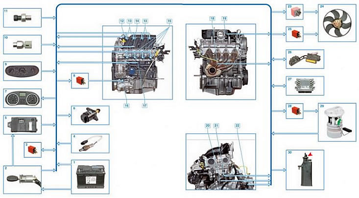
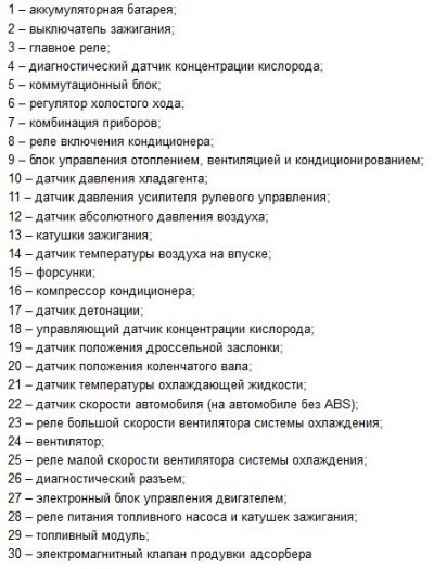
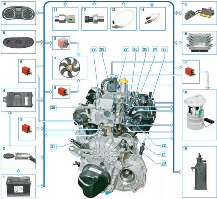
Elements of the electronic engine management system 1.6 (16V):

Scheme of the electronic engine management system 1.6 (16V):
Elements of the ECM 1.6 (8V) (air filter removed):
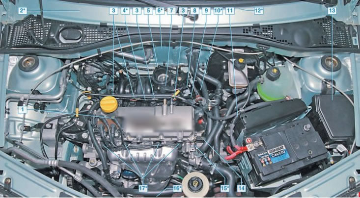

ECM scheme 1.6 (8V):
Electronic engine control unit (ECU)
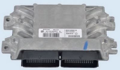
The ECU receives all the necessary information from the sensors and controls the actuators. As in most Renault cars, on a Lada Largus car, the ECU is installed in the engine compartment on a bracket behind the battery. It is an electronic unit type EMS 31.32 with a 90-pin interface connector. (ECU replacement)
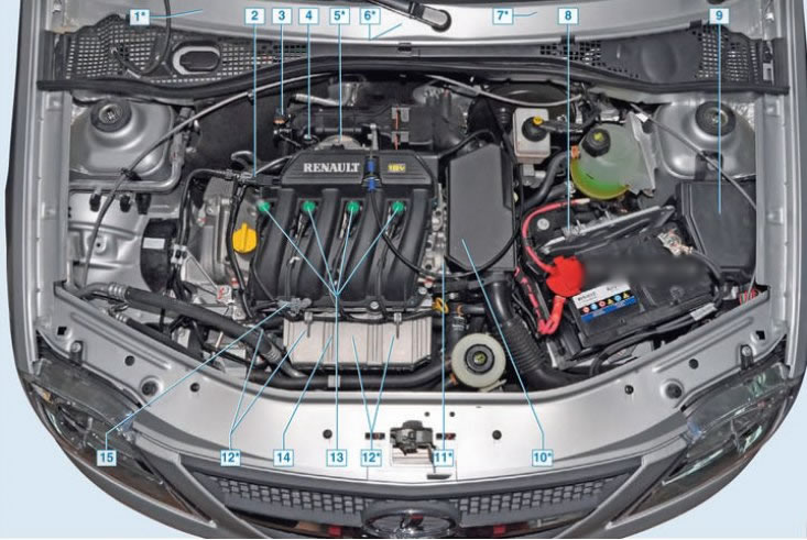
The figures above show a general view of the engine compartment with the location of the ECM elements, including the ECU. as well as elements of electrical equipment of the car.
The ECU includes a microcontroller with built-in Flash-memory (programmable read only memory (PROM)) and working memory (RAM), ADC chips, drivers for controlling the operation of the engine of the idle speed controller (IAC), fuel pump control signal, etc. The microcontroller generates the supply voltage for the heater of the oxygen and air flow sensors. After turning on the ignition, the controller turns on the indicator. located in the instrument cluster, which informs the driver about the serviceability or detection of any malfunction of the ECM.
External diagnostic equipment is connected to the socket for information communication with the controller via a bidirectional K-line.
In RAM when power off (battery) information is not stored, unlike PROM, which is a non-volatile device.
Lamp (indicator) on the instrument cluster, signaling a malfunction of the ECM
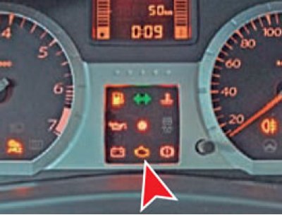
Do not operate the vehicle with a permanently lit (flashing) ECM malfunction indicator. The car is allowed to move to the place of repair. If the malfunction is short-term, then the light will go out after 10 seconds, provided that there are no other fault codes in the computer memory that cause this warning lamp to turn on.
Diagnostic connector
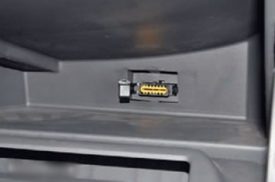
Diagnostic connector (diagnostic block) located in the glove box on its rear wall. With it, fault codes located in the ECU can be read. The figure shows the location of the diagnostic connector, and the pin assignment is shown in the table below.
Pinout of the diagnostic connector
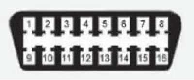
Table: Pin assignment of the diagnostic connector
| Contact number | Purpose |
| 1 | Tire «+» after turning on the ignition |
| 2, 3 | Earth |
| 6 | Not used |
| 7 | Diagnostic signal K (bus K-line) |
| 8-14 | Not used |
| 15 | Diagnostic signal L (bus K-line) |
| 16 | Tire «+» battery |
Engine position and speed sensor (DPKV)
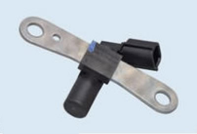
The crankshaft position and speed sensor is an inductive type, it is designed to synchronize the operation of the electronic ECU system with the angular position of the crankshaft and the first cylinder of the engine. The sensor is located at the rear of the engine opposite the master ring on the engine flywheel. The driving ring is a gear wheel. To synchronize work on the disk, two teeth are missing - this is the starting point.
When the drive disk rotates, alternating current pulses are generated in the sensor winding, the signal is fed directly to the computer.
If the sensor fails, starting the engine is impossible, the sensor is checked in the following order:
- check the integrity of the connections;
- disconnect the connector block and measure the resistance of the sensor winding, it should be in the range of 200... 270 Ohm;
- if the winding resistance is normal, a process connector is connected to the sensor and the sensor output signal is checked using an oscilloscope - the pulse amplitude must be at least 0.9 V, otherwise the sensor is replaced.
It is located on the clutch housing, above the engine flywheel.
Inlet air temperature sensor (DTV)
The temperature sensor incorporates a thermistor, it is installed in the intake manifold. A reference voltage of 5 V is supplied from the computer through a current-limiting resistor to the sensor. The intake air temperature is calculated from the voltage drop across the sensor. The ECU uses the readings from this sensor to calculate the duration of the fuel injector opening pulses and the ignition timing.
On the engine 1.6 (16V) located in the front of the receiver.
On the engine 1.6 (8V) installed in the intake manifold on the left.
Coolant temperature sensor (DTOZH)
The coolant sensor is similar in design to the previous sensor - it is a thermistor, the resistance of which changes inversely with the temperature of the coolant. The sensor is mounted on the cylinder block, in its rear part. From the voltage drop across the sensor, the ECU determines the temperature of the engine and takes it into account when calculating the parameters of the injection and ignition system.
On the engine 1.6 (16V) located in the opening of the thermostat housing located on the left side of the cylinder head.
On the engine 1.6 (8V) located in the hole on the left side of the cylinder head.
Phase sensor (camshaft position)
The inductive type phase sensor is installed only on the K4M motor, its operation is based on the Hall effect. The sensor is mounted on the back of the cylinder head cover. When passing through the edge sensor of the drive disk mounted on the camshaft, the magnetic field changes and alternating current voltage pulses are generated. The signal from the sensor is sent to the ECU to ensure the operation of phased fuel injection in accordance with the order of operation of the internal combustion engine cylinders. If a malfunction occurs in the sensor, the ECU stores an error code in memory and turns on the indicator light located on the instrument cluster.
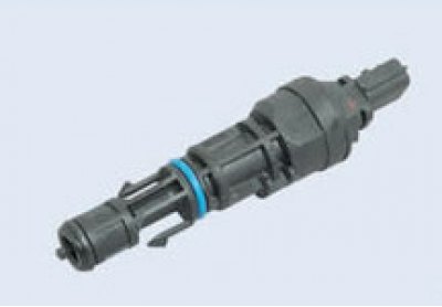
Throttle position sensor (TPS)
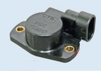
Located on the axis of the throttle valve assembly (replacement).
Knock sensor (DD)
On the engine 1.6 (16V) located in the hole on the front wall of the cylinder block, located in the area between the 2nd and 3rd cylinders.
On the engine 1.6 (8V) located in the hole on the back wall of the BC, in the area of the 3rd cylinder.
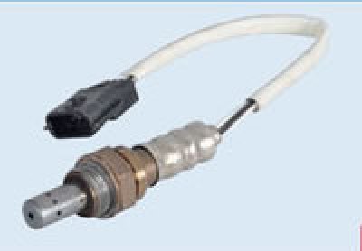
Control oxygen sensor (UDCC)
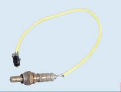
Installed in the threaded hole of the exhaust manifold. (replacement).
Diagnostic oxygen sensor (DDCC)
Installed in the exhaust pipe after the catalytic converter. (replacement).
Absolute air pressure sensor (DBP)
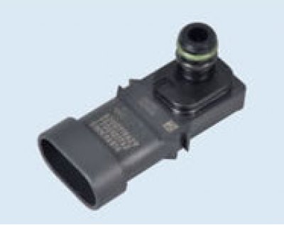
On the engine 1.6 (16V) installed in the receiver on the right.
On the engine 1.6 (8V) installed in the intake manifold on the left.
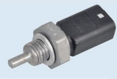
Vehicle speed sensor (DSA)
Mounted on top of the gearbox housing.