



Electrical diagrams of the fuel injection system for Euro-2 and Euro-3 toxicity standards are given below.
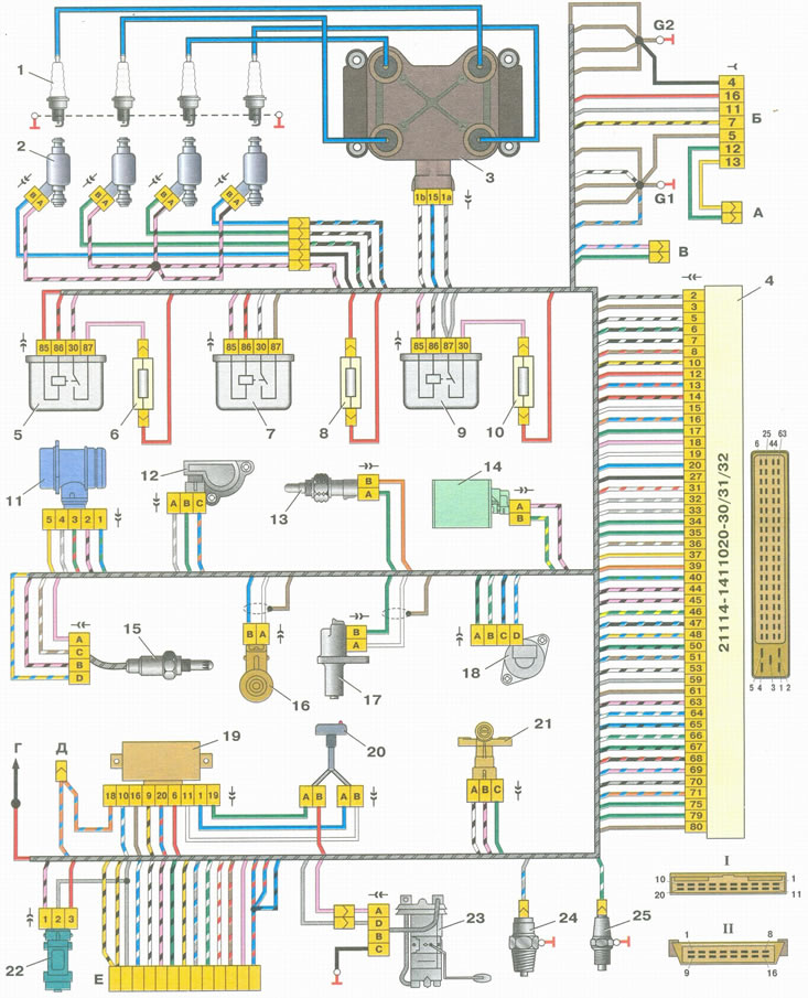
Engine management system connections for Euro-2 toxicity standards: 1 - spark plugs; 2 - injectors; 3 - ignition coil; 4 - controller; 5 - main relay; 6 - Main relay circuit fuse; 7 - Electric fan relay; 8 - Electric fan circuit fuse; 9 - Electric fuel pump relay; 10 - Electric fuel pump circuit fuse; 11 - mass air flow sensor; 12 - throttle position sensor; 13 - coolant temperature sensor; 14 - Evaporative Evaporative Blow-Off Solenoid Valve; 15 - oxygen concentration sensor; 16 - knock sensor; 17 - crankshaft position sensor; 18 - idle speed control; 19 - immobilizer control unit; 20 - immobilizer status indicator; 21 - phase sensor; 22 - speed sensor; 23 - Fuel pump module; 24 - Oil pressure warning light sensor; 25 - coolant temperature gauge sensor; A - connector connected to the harness of the anti-lock braking system (ABS); B - diagnostic connector; B - connector connected to the air conditioner wiring harness; G - to the "+" terminal of the battery; D - to the side door wiring harness connector; E - connector connected to the instrument panel wiring harness; G1, G2 - grounding points; I - the order of conventional numbering of contacts in the connector of the wires of the immobilizer control unit; II - the order of conventional numbering of contacts in the diagnostic connector
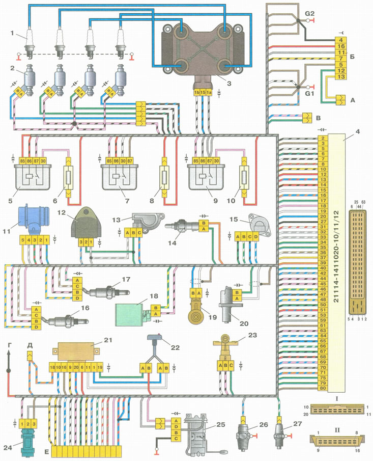
Engine management system connections for Euro-3 toxicity standards: 1 - spark plugs; 2 - injectors; 3 - ignition coil; 4 - controller; 5 - main relay; 6 - Main relay circuit fuse; 7 - Electric fan relay; 8 - Electric fan circuit fuse; 9 - Electric fuel pump relay; 10 - Electric fuel pump circuit fuse; 11 - mass air flow sensor; 12 - Rough road sensor; 13 - throttle position sensor; 14 - coolant temperature sensor; 15 - idle speed control; 16 - oxygen concentration control sensor; 17 - diagnostic oxygen concentration sensor; 18 - Evaporative Emissions Blow-off Solenoid Valve; 19 - knock sensor; 20 - crankshaft position sensor; 21 - immobilizer control unit; 22 - immobilizer status indicator; 23 - phase sensor; 24 - speed sensor; 25 - fuel pump module; 26 - Oil pressure warning light sensor; 27 - coolant temperature gauge sensor; A - connector connected to the harness of the anti-lock braking system (ABS); B - diagnostic connector; B - connector connected to the air conditioner wiring harness; G - to the "+" terminal of the battery; D - to the side door wiring harness connector; E - connector connected to the instrument panel wiring harness; G1, G2 - grounding points; I - the order of conventional numbering of contacts in the connector of the wires of the immobilizer control unit; II - the order of conventional numbering of contacts in the diagnostic connector
(Data obtained from the website LADAMAN.RU)