
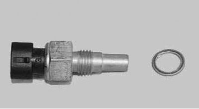
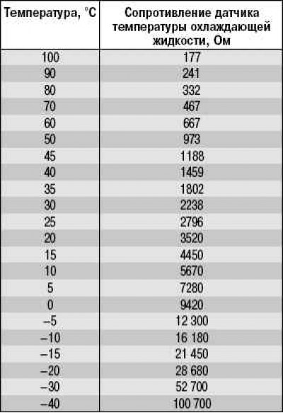
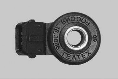
The coolant temperature sensor is a thermistor (resistor whose resistance changes with temperature). The sensor is screwed into the thermostat housing and connected to the computer. At low temperature, the resistance of the sensor is high, and at high temperature, the resistance is low (tab. 10.5).
The ECU calculates the coolant temperature from the voltage drop across the sensor. On a cold engine, the voltage drop is high, and on a warm engine, it is low.
Table 10.5. Dependence of the resistance of the coolant temperature sensor on temperature
Coolant temperature affects most of the characteristics controlled by the ECU.
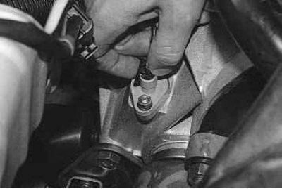
You will need a key to replace the sensor «at 19».
1. Disconnect the wire from the terminal «minus» battery.
2. Partially drain the coolant from the radiator.
3. For ease of operation, remove the air filter (see «Removal and installation of the air filter»).
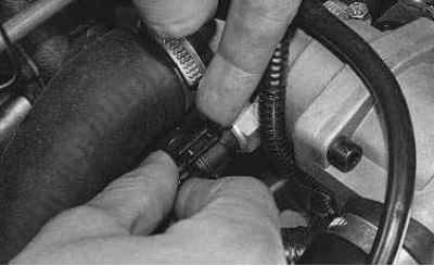
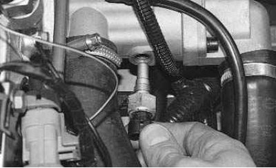
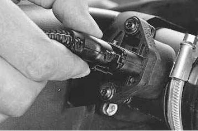
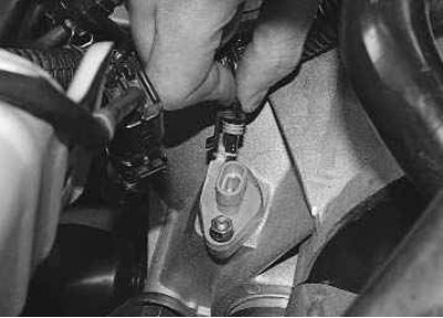
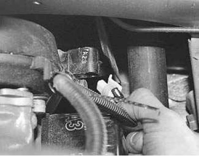
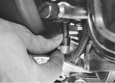
4. Press out the plastic retainer...
5.... and disconnect the wiring harness connector from the coolant temperature sensor.
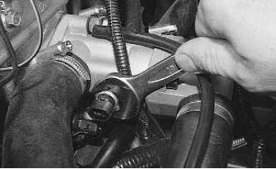
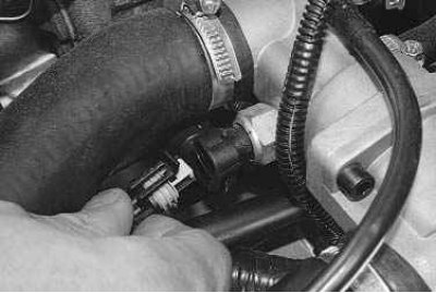
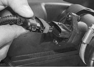
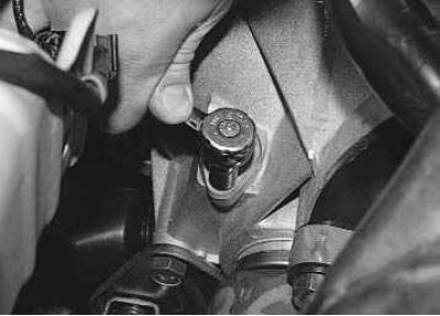
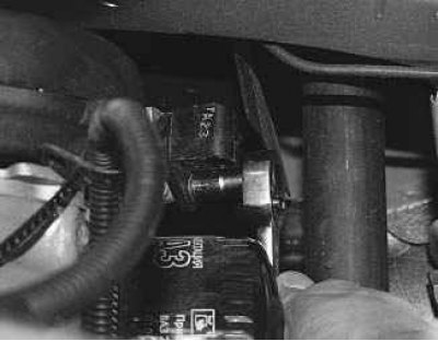
6. Loosen the sensor tightening with a wrench...
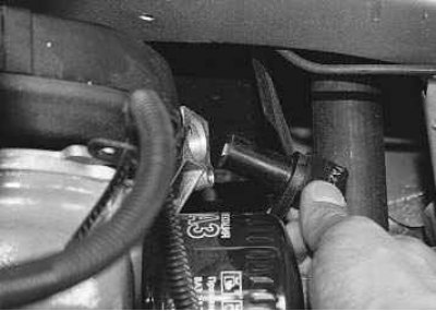
7.... and unscrew it from the thermostat housing.
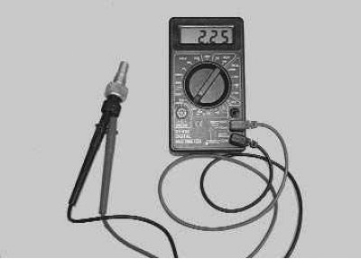
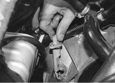
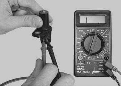
8. Cool the sensor down to ambient temperature. Connect the tester in ohmmeter mode to the sensor terminals and measure its resistance. Measure the current air temperature with a thermometer and compare the obtained values \u200b\u200bwith the table. 10.5. If the resistance deviates from the norm, replace the sensor.
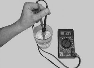
9. To measure the resistance at the sensor terminals under various temperature conditions, lower the sensor into hot water and check the change in its resistance as the water cools, controlling the water temperature with a thermometer. Nominal resistance values at various temperatures are shown in Table. 10.5.
10. Install the sensor in the reverse order of removal.
11. Fill in coolant.
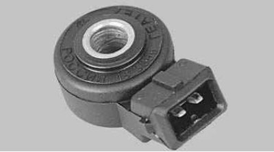
Knock sensor, attached to the top of the cylinder block, picks up abnormal vibrations (detonation strikes) in the engine.
The sensitive element of the sensor is a piezoelectric plate. When detonation occurs, voltage pulses are generated at the sensor output, which increase with increasing intensity of detonation impacts. The ECU, based on the signal from the sensor, regulates the ignition timing to eliminate detonation flashes of fuel.
You will need a key to replace the sensor «at 13».
1. Disconnect the wire from the terminal «minus» battery.
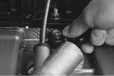
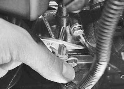
2. Press the metal clamp of the wiring harness block...
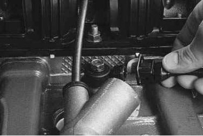
3.... and disconnect the block from the knock sensor. For clarity, the crankcase ventilation hose has been removed.
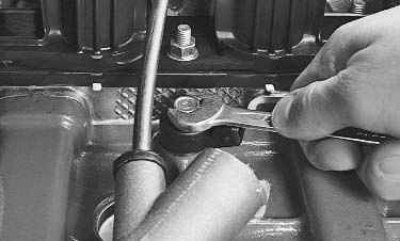
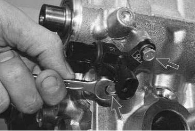
4. Loosen the knock sensor mounting bolt with a wrench...
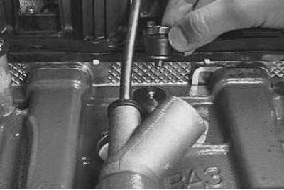
5.... and, having unscrewed the bolt by hand, remove it together with the knock sensor.
Note. Pay attention to the marking of the sensor in order to purchase a similar knock sensor for replacement.
6. Install the sensor in the reverse order, screwing in the bolt of its fastening and tightening it with a torque of 10.4–24.2 Nm.
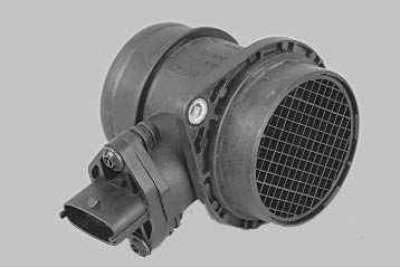
Mass air flow sensor (DMRV) located between the air filter and the air supply sleeve.
The sensor signal is a DC voltage, the value of which depends on the amount of air passing through the sensor.
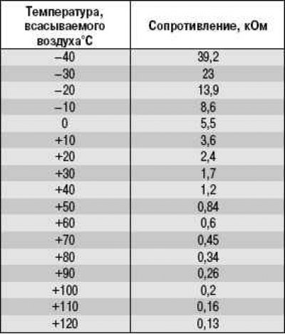
An air temperature sensor is built into the DMRV, the sensitive element of which is a thermistor installed in the air stream. At low temperature, the resistance of the sensor is high, and at high temperature, the resistance is low (tab. 10.6).
Table 10.6. The dependence of the resistance of the air temperature sensor on the temperature of the intake air (allowable error 10%)
If the air temperature sensor is faulty, the ECU memorizes the error code and turns on the signal lamp, and replaces the readings of the faulty sensor with a fixed air temperature value of 33°C.
To replace the sensor you will need: a key «on 10», Phillips screwdriver.
1. Disconnect the wire from the terminal «minus» battery.
2. Pressing the plastic latch from the bottom with a screwdriver or finger...
3.... Disconnect the wiring harness block from the mass air flow sensor.
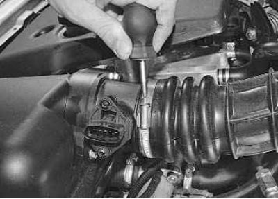
4. Loosen the air hose clamp...
5.... and disconnect the sleeve from the sensor.
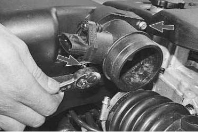
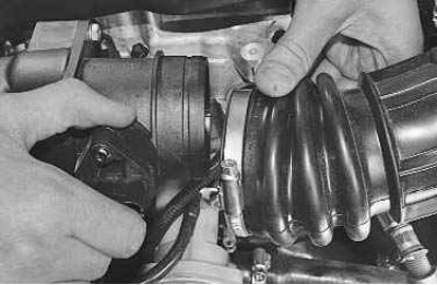
6. Turn off two screws of fastening...
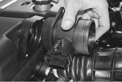
7.... and remove the sensor from the air filter.
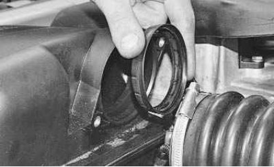
8. Remove the rubber gasket and carefully inspect the condition of its edges, as damage to them can lead to air leaks bypassing the air filter. During movement, the air contains many small mechanical particles that can damage the DMRV and, as a result, lead to interruptions in the operation of the engine.
9. Before installing the sensor, first put the rubber seal on it and only then fix the sensor to the air filter.
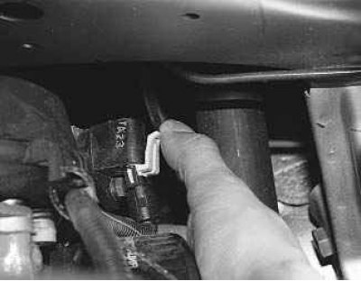
Vehicle speed sensor installed on the gearbox. When the drive wheels rotate, the speed sensor generates 6 pulses per 1 m of the vehicle's run, and the ECU determines the vehicle's speed by the frequency of the pulses.
You will need a key to replace the sensor «on 10».
1. Disconnect the wire from the terminal «minus» battery.
2. Press the latch...
3.... and disconnect the block with wires from the speed sensor.
4. Turn away a nut of a hairpin of fastening of the sensor of speed...
5.... and remove the sensor from the gearbox housing.
6. Install the sensor in the reverse order of removal.
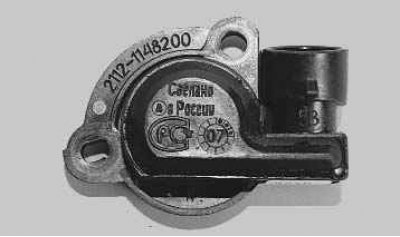
Throttle position sensor (TPS) mounted on the side of the throttle assembly and connected to the throttle valve axis. It is a potentiometer, one end of which is supplied with «plus» supply voltage (5 V), its other end is connected to «weight». From the third output of the potentiometer (from the slider) is the output signal to the ECU. When the throttle is turned (from impact on the control pedal), the voltage at the output of the sensor changes. When the throttle is closed, it is below 0.6 V. When the throttle opens, the voltage at the sensor output rises and should be more than 4.4 V when the throttle is fully open. By monitoring the output voltage of the sensor, the ECU adjusts the fuel supply depending on the throttle opening angle (those. at the request of the driver). TPS does not require adjustment, as the electronic unit perceives idling (those. full throttle closing) as a zero point.
If the throttle sensor fails, the ECU memorizes the sensor's fault code, turns on the warning light «CHECK ENGINE» and calculates the estimated value of the throttle opening angle from the crankshaft speed and the DMRV signal.
To replace the sensor, do the following.
1. Disconnect the wire from the terminal «minus» battery.
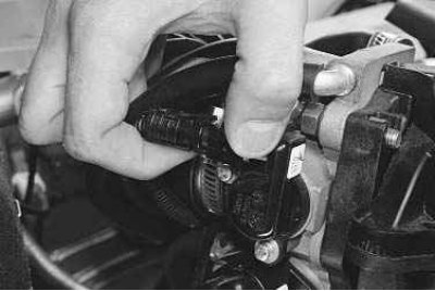
2. Press the latch...
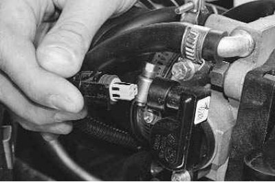
3.... and disconnect the wiring harness connector from the sensor leads.
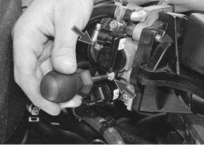
4. Turn out two screws of fastening...
5.... and remove the throttle position sensor from the throttle assembly.
6. Install the sensor in the reverse order of removal. Pay attention to the condition of the foam rubber sealing ring: if it is damaged, replace it with a new one.
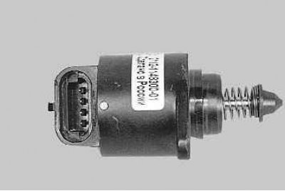
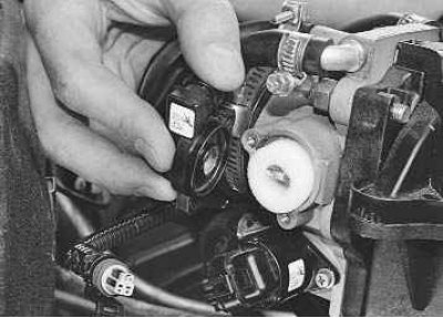
idle speed controller (IAC) regulates the idle speed of the crankshaft by controlling the amount of air supplied to bypass the closed throttle. It consists of a two-pole stepper motor and a cone valve connected to it. The valve extends or retracts according to the signals from the ECU. Fully extended regulator needle (which corresponds to 0 steps) blocks the air flow. When the needle is retracted, an air flow is provided that is proportional to the number of steps the needle moves away from the seat.
IAC replacement is described in sec. «Engine» (see «Replacement of the regulator of idling», With. 134).
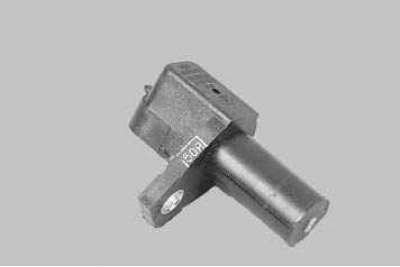
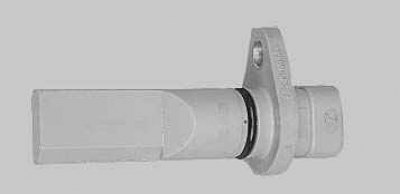
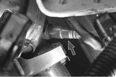
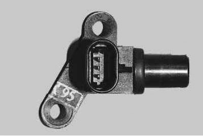
crankshaft position sensor inductive type, designed to measure the speed and position of the crankshaft. The sensor is mounted on the cover of the oil pump opposite the setting disk on the alternator drive pulley. The driving disk is a gear wheel with 58 equidistant (6°) depressions. With this pitch, 60 teeth are placed on the disc, two teeth are sheared to create a synchronization pulse («reference» momentum), which is necessary to coordinate the operation of the controller with the TDC of the pistons in the 1st and 4th cylinders.
As the crankshaft rotates, the teeth change the sensor's magnetic field, inducing AC voltage pulses. The installation gap between the sensor core and the disc tooth must be within (1±0,2) mm. The ECU sends pulses to the injectors based on the signals from the sensor.
You will need a key to replace the sensor «on 10».
1. Disconnect the wire from the terminal «minus» battery.
2. Press the latch...
3.... and disconnect the block with wires from the crankshaft position sensor.
4. Turn out a bolt of fastening...
5.... and remove the sensor from its mounting bracket.
6. Measure the resistance of the sensor. The resistance of a good sensor should be 500-700 ohms. If the tester readings are much lower, then there is probably an interturn short circuit in the winding, and if, on the contrary, it is high or the tester shows infinity (see photo), then the contacts inside the sensor are broken or there is a break in the winding of the induction coil. Both in the first and in the second case, the sensor must be replaced.
7. Install the sensor in the reverse order of removal.
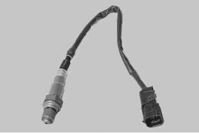
Control oxygen sensor It is used in the feedback fuel injection system and is installed in the upper part of the manifold. To correct the calculations of the duration of the injection pulses, information is used on the presence of oxygen in the exhaust gases, this information is provided by the control oxygen concentration sensor. The oxygen contained in the exhaust gases reacts with the oxygen sensor, creating a potential difference at the output of the sensor. It varies from approximately 0.1 V (high oxygen content - lean mixture) up to 0.9 V (little oxygen - rich mixture).
For normal operation, the temperature of the sensor must be at least 300°C. Therefore, for quick warm-up after starting the engine, a heating element is built into the sensor.
By monitoring the output voltage of the oxygen concentration sensor, the controller determines which command to adjust the composition of the working mixture to apply to the injectors. If the mixture is lean (low potential difference at the sensor output), then the controller gives a command to enrich the mixture; if the mixture is rich (high potential difference) - to lean the mixture.
You will need a key to replace the control oxygen sensor «at 22».
1. Disconnect the wire from the terminal «minus» battery.
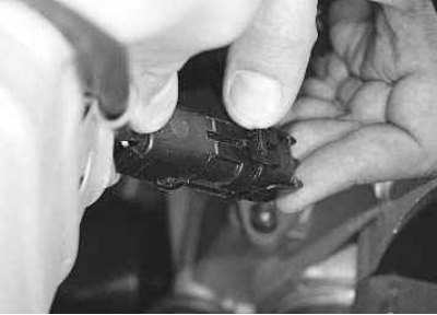
2. Press the latch...
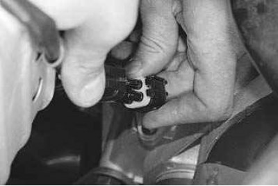
3.... and disconnect the block of the wiring harness of the control oxygen concentration sensor from the engine harness.
4. Disconnect from a heat-insulating guard of the steering mechanism the holder of a plait of wires of the operating gauge of concentration of oxygen.
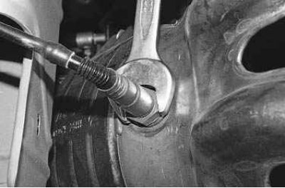
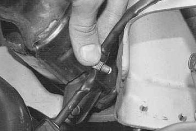
5. Unscrew the sensor from the collector...
6.... and remove from the vehicle.
Note. To remove the sensor, use special heavy-duty hex wrenches. They can look like ring wrenches or be in the form of a high end head with a split sector for threading a wiring harness into it.
7. Install the sensor in the reverse order of removal, having previously lubricated the threaded part of the sensor with graphite grease.
Diagnostic oxygen sensor installed in the collector behind the neutralizer, it works on the same principle as the control sensor, and is completely interchangeable with it. The signal generated by the diagnostic oxygen concentration sensor indicates the presence of oxygen in the exhaust gases after the converter. If the converter is working properly, the readings of the diagnostic sensor will differ significantly from the readings of the control sensor.
The replacement of the diagnostic oxygen concentration sensor is carried out in the same way as the replacement of the control sensor.
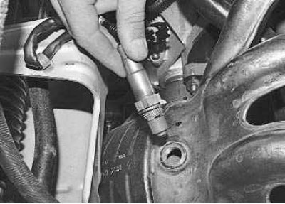
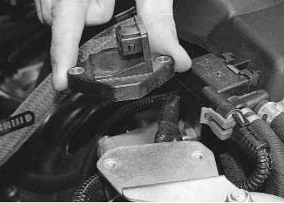
Phase sensor installed on the rear cover of the camshaft drive. The principle of its operation is based on the Hall effect. On the camshaft pulley (inlet) Spot-welded drive disc with special groove (ledge). When the disk passes through the sensor slot, a low voltage pulse is sent from the sensor to the ECU (approximately 0 V), and when it hits «measuring» area of the sensor of the ledge of the driving disk on the computer, a pulse occurs «reference» voltage (about 5 V), which corresponds to the position of the piston of the 3rd cylinder in the compression stroke.
To replace the phase sensor, you will need a socket wrench «on 10».
1. Disconnect the wire from the terminal «minus» battery.
2. Press the latch...
3.... and disconnect the wiring harness block from the phase sensor.
4. Turn out two bolts of fastening of the gauge...
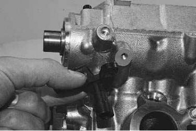
5.... remove the sensor (for clarity, the turning out of the bolts with an open-end wrench on a removed and partially disassembled engine is shown).
6. Install the sensor in the reverse order of removal.
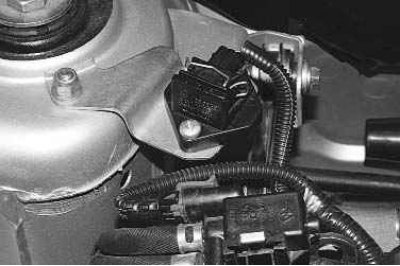
Rough road sensor installed in the engine compartment on the cup of the right mudguard. The principle of operation of the sensor is based on the piezoelectric effect. When driving on a rough road, a variable load affects the angular velocity of the crankshaft. The fluctuations in the crankshaft speed are similar to the fluctuations that occur during misfires.
The rough road sensor measures the amplitude of the car body vibrations and sends a signal to the controller. If the signal threshold is exceeded, the controller disables the misfire diagnostic function.
You will need a Phillips screwdriver to remove the rough road sensor.
1. Disconnect the wire from the terminal «minus» battery.
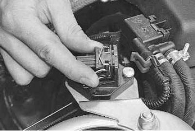
2. Squeeze the spring clip...
3.... and disconnect the wiring harness connector from the sensor leads.
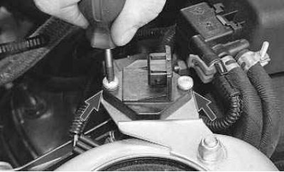
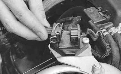
4. Remove two screws securing the sensor to the bracket...
5.... and remove the sensor.
6. Install the sensor in the reverse order of removal.