



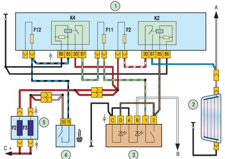
Figure 10.11. Rear window heating element connection diagram: 1 – mounting block; 2 – rear window heating element; 3 – rear window heating switch; 4 – ignition switch (lock); 5 – main fuse box; A – to the electrical package control unit, terminal "10"; B – to the lighting control module (instrument lighting controller), terminal "58b"; C – to the positive terminal of the battery; K4 – additional relay (ignition relay); K2 – relay for switching on the rear window heating
The diagram of the rear window heating system is shown in the figure 10.11.
The rear window heating element is switched on using relay K2, installed in the mounting block.
To prevent the battery from being discharged by the heating element left on when the engine is not running, the heating can only be turned on when the ignition is on. For this purpose, power is supplied to switch 3 through an additional relay (ignition relay) K4, which is triggered when the ignition is turned on, and fuse F11. Power is supplied to the heating element through fuse F2 in the mounting block located in the vehicle's interior.
If the rear door glass does not heat up when the heating is turned on, check fuses F2 and F11 in the mounting block, fuse F2 in the main fuse block, wires and their connections, switch and relay K2.
If all fuses, relays and heating element power supply circuit are good, check the condition of the conductive strips.
The check is carried out with the engine running and the rear window heating on. Measure the voltage on all strips one by one using a voltmeter, connecting one terminal of the voltmeter to the body ground and the other in series to the conductive strips. If the voltage measured by the voltmeter at the beginning and end of the stripes is the same and approximately equal to the battery voltage, check the reliability of the contact of the "ground" wire of the heating element with the car body.
The voltage on the strip should decrease as the voltmeter connection point moves away from the positive polarity bus of the element. The voltage must be measured in at least two places at the same distance from the axis of symmetry to exclude the possibility of missing a damaged area. If you find a discrepancy in the readings on one of the bands, move the contact of the voltmeter wire along this band until the voltage becomes zero. A sharp drop in voltage indicates a break in the strip at this location. Mark the location of the break on the outer surface of the glass with chalk or a glass marker for subsequent repair of the damaged area.
To repair the heating element, you can use one of the special kits available on the market that contain silver. Despite the fact that the kits are made by different manufacturers, their composition is approximately the same, all kits are supplied with instructions for use. Below is a typical procedure for working with these sets.
1. Remove a 6mm long section of the strip from each side of the damaged area.
2. Wipe the damaged area with a clean cloth soaked in alcohol.
3. Apply repair adhesive tape or two pieces of regular adhesive tape to the glass at the damaged strip location, above and below the area being repaired, with the distance between the pieces of adhesive tape corresponding to the width of the conductive strip on the glass.
4. Mix the hardener thoroughly with the silver base compound. If the hardener has thickened, place the package in hot water and wait until the hardener becomes liquid.
5. Apply the composition to the area to be repaired using a wooden spatula and remove the adhesive tape.
6. Place the heater at a distance of 25 mm from the damaged area and heat the composition for 1–2 minutes. The minimum heating temperature is 149°C.
Note: In some kits, the composition does not need to be heated: it polymerizes at room temperature.
7. If the strip becomes discolored after drying, apply a tinting iodine composition to it with a brush - the color of the strip will be restored. After the iodine mixture has dried for 30 seconds, wipe off any excess with a clean, lint-free cloth. During the polymerization of the repair composition, which lasts 24 hours, avoid any mechanical impact on the repaired section of the strip.
8. Turn on and check the operation of the rear window heating element.
If the wire has come off the busbar, solder it with solder containing 3% silver and rosin paste as flux in the following order.
1. Clean the soldering area on the busbar and the wire core.
2. Using a brush, apply a little rosin paste to the areas of the wire and busbar to be connected.
3. Apply a thin layer of solder to the wire core.
4. Solder the wire to the busbar, avoiding overheating of the parts being connected.