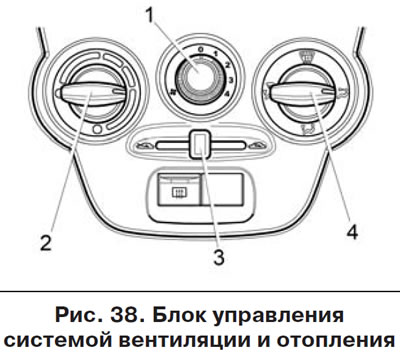
- 1 - handle for switching the operating modes of the heating and ventilation unit fan.
- 2 - handle for setting the temperature mode of the heating and ventilation unit.
- 3 - recirculation mode control handle.
- 4 - air flow distributor control handle.
The vehicle's heating and ventilation system is designed to create a comfortable air temperature in the passenger compartment, the value of which is regulated by the ventilation and heating system control unit (figure 38). However, it cannot provide a temperature in the cabin lower than the outside air.
In the variant version, the air intake box of the heating and ventilation unit contains an air filter, which is designed to clean the air entering the car interior from dust, pollen, soot and small insects. The filter is replaced and the drainage hole in the front shield is cleaned at certified service stations every 15,000 km (when operating on dusty roads - as needed).
Warning!
- Correct use of the controls of the heating and ventilation system in accordance with the recommendations below improves driving safety by quickly clearing the glass of snow and ice, as well as eliminating fogging.
- Remember - fast cleaning of glass and the most efficient heating of the interior are possible only with a fully warmed-up engine!
Handle 3 of the recirculation flap control lever serves to supply outside air to the passenger compartment, and it is in the extreme left position
 , and in the position
  handle 3 in the extreme right position shuts off the supply of outside air to the vehicle interior (recirculation mode). This mode can be used when driving through a tunnel or in a traffic jam to prevent exhaust gas-saturated air from entering the passenger compartment, as well as to quickly warm up the air in the passenger compartment (for example in parking lots).
Warning! The recirculation mode can only be switched on for a short time, as this prevents fresh air from entering the passenger compartment and may cause the windows to fog up.
To increase the air supply to the vehicle interior, move the handle 1 of the heater electric fan mode switch to one of four positions. Position 1 is the minimum air supply speed to the cabin, positions 2 and 3 are medium speeds, and position 4 is the maximum. In the switch position 0, the fan does not work and there is no supply of fresh air to the passenger compartment.
Attention! When driving with the windows closed, it is recommended to turn on the fan of the heating and ventilation system to create excess pressure in the passenger compartment (to prevent dust from getting in through gaps in the body), and also to prevent the glass from fogging up.
Handle 4 of the control unit serves to distribute the air supply and can be set to any intermediate position (between the symbols described below) for more precise adjustment of air supply distribution.
If handle 4 is installed with its white mark opposite the symbol
 air enters the lower part of the cabin, into the driver's and passenger's footwell areas.
If handle 4 is installed with its mark opposite the symbol
 , air enters the lower part of the passenger compartment, into the areas of the driver and passengers' feet, as well as through the windshield defroster nozzles and the front door window defroster nozzles.
If handle 4 is installed with its mark opposite the symbol
 , air enters through the windshield blower nozzles and the front door window blower nozzles.
If handle 4 is installed with its mark opposite the symbol
 , air enters through the side and central nozzles into the upper part of the car interior to blow air onto the driver and passengers.
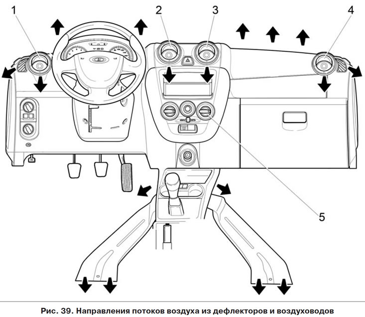
Direct impact on nozzle deflectors 1, 2, 3 and 4 (figure 39) the intensity of air supply is regulated by changing the position of the deflectors until they are completely closed. The required nozzle is opened by pressing on a special recess in the deflector. By rotating the deflector the direction of the air flow is adjusted.