
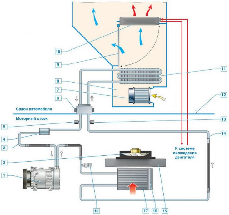
General scheme of the ventilation, heating and air conditioning system: 1 - air conditioning compressor; 2 - radiator fan; 3 - low pressure pipeline (TND); 4 - damper; 5 - valve designed for charging / discharging refrigerant in LPT; 6 - reducer; 7 - stove fan; 8 - stove body; 9 - damper regulating temperature; 10 - stove radiator; 11 - evaporator; 12 - body shield separating the passenger compartment and the engine compartment; 13 - valve for filling and releasing coolant in the theater; 14 - TVD; 15 - engine radiator; 16 - receiver-drier; 17 - capacitor; 18 - refrigerant pressure sensor
Air conditioning unit shown Here.
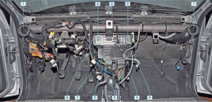
Location of air ducts of the heating, ventilation and air conditioning system (dashboard removed for clarity): 1 - side air ducts; 2 - windshield air duct; 3 - central air ducts; 4 - electric motor of the stove fan; 5 - air ducts to the feet of the driver and front passenger; 6 - air ducts going to the legs of the rear seat passengers; 7 - heater (stove); 8 - additional heater fan resistor
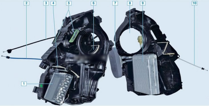
Heater - stove (hull disassembled): 1 - stove radiator; 2 – a cable of a gate of a regulator of temperature; 3 - air recirculation damper cable; 4 - damper of the temperature controller; 5 - air distribution damper; 6 - air recirculation damper; 7 - sealant; 8 – fan socket; 9 - air conditioner evaporator; 10 – a cable of air-distributing dampers
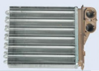
Heater radiator - stove. Coolant circulates through it. Air passes either through the radiator, bypassing it in any way, depending on what air temperature is set on the regulator.
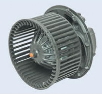
The heater fan is used to supply outside air to the passenger compartment.
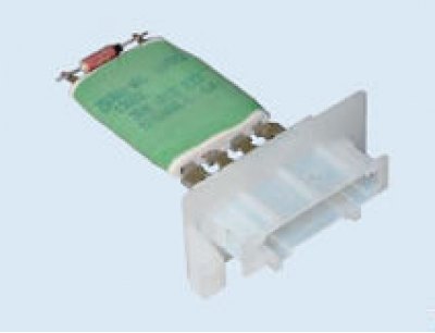
Additional heater fan resistor - with its help, the fan can rotate at 4 different speeds.