
Removing
Remove instrument panel (see here).
Drain coolant (see here).
For vehicles equipped with an air conditioning system, unload the refrigerant from the air conditioning system in accordance with the operating instructions for the service equipment.
Unscrew two bolts 1, Figure 13-1, of the lower fastening of the reinforcement 2 of the instrument panel cross member to the body base (interchangeable head 13, knob).
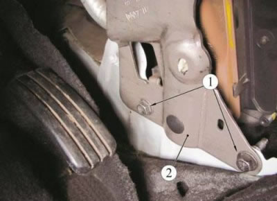
Figure 13-1 - Lower fastening of the instrument panel cross member reinforcement: 1 - a bolt of fastening of the amplifier of a cross-beam of the panel of devices; 2 - amplifier of the cross member of the instrument panel
Unscrew the two nuts 1, Figure 13-2, of the upper fastening of the amplifier 2 of the instrument panel cross member. Disconnect the block 3 of the wiring harness and remove the amplifier 2 (interchangeable head 13, knob).
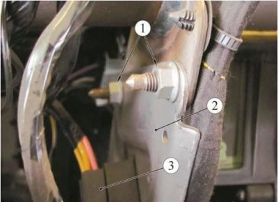
Figure 13-2 - Upper fastening of the instrument panel cross member reinforcement: 1 - nut for fastening the amplifier of the instrument panel cross member; 2 - amplifier of the cross member of the instrument panel; 3 - wiring harness block
Compress and move two clamps 4, Figure 13-3 (clamp puller type 10614 "Stahlwille").
Remove heater inlet 2 and outlet 1 hoses from heater radiator branch pipes 3.
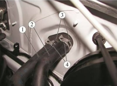
Figure 13-3 - Fixing the heating hoses: 1 - heater outlet hose; 2 - heater supply hose; 3 - heater radiator pipes; 4 - collar
Loosen two screws 2, Figure 13-4, fastening the air distribution unit 1 to the cross member 3 (interchangeable head Torx Т20, knob).
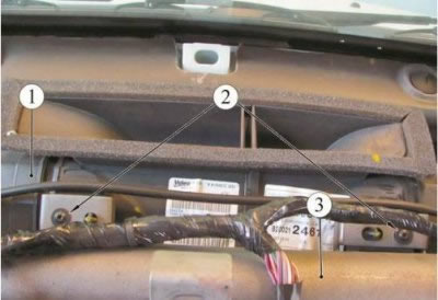
Figure 13-4 - Fastening the air distribution unit to the cross member of the instrument panel: 1 - air distribution block; 2 - screw for fastening the block to the cross member; 3 - cross member of the instrument panel
Unscrew screw 4, Figure 13-5, fastening the left front air duct and remove the air duct, similarly remove the right air duct (interchangeable head Torx T20, extension, knob).
Unscrew two screws 2 securing the cross member 1 of the instrument panel on the right and left, remove the cross member (interchangeable head 13, knob).
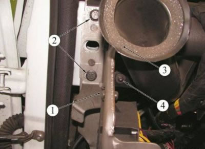
Figure 13-5- Fastening the cross member of the instrument panel and the left front air duct: 1 - cross member of the instrument panel; 2 - cross member fastening screw; 3 - front air duct; 4 - air duct fastening screw
For vehicles equipped with an air conditioning system: from the engine compartment, unscrew two bolts 1, Figure 13-6, fastening the pipelines to the evaporator, disconnect the connections and install technological plugs on the pipelines and the evaporator unit (interchangeable head 10, extension, crank).
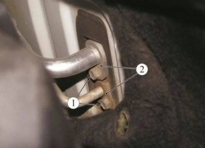
Figure 13-6 - Fixing the evaporator piping: 1 - bolt for fastening fittings of pipelines; 2 - pipelines of the air conditioning system
Disconnect the wiring harness pads from the fan, additional resistor.
Remove the heater block assembly with the heating, air conditioning and ventilation control unit.
Installation
Installation is carried out in the reverse order of removal, while:
- for vehicles equipped with an air conditioning system: remove the plugs from the pipes and the evaporator unit, install new O-rings on the pipes. Apply compressor oil to the sealing rings;
- evacuate the air conditioning system and load the system with refrigerant, according to the operating instructions for the service equipment.
Check the operation of the heating, air conditioning and ventilation system.
Disassembly
Remove the heating, air conditioning and ventilation control unit by disconnecting the damper drive rods from the heater unit.
Remove foam seals 2, Figure 13-7.
Unscrew two screws 3 and remove the pipe bracket 1 (interchangeable head Torx T20, extension, knob).
Unscrew screw 4 and remove inlet pipes 7 and outlet pipes 8 of heater radiator 6 (interchangeable head Torx T20, extension, knob).
Unscrew two screws 5, unscrew three clamps, remove the radiator 6 from the heater body and drain the remaining coolant (interchangeable head Torx Т20, knob).
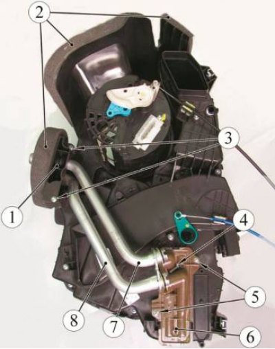
Figure 13-7 - Heater unit: 1 - branch pipe bracket; 2 - foam seals; 3 - screw for fastening the branch pipe bracket; 4 - screw for fastening pipes; 5 - radiator mounting screw; 6 - radiator; 7 - inlet pipe; 8 - outlet pipe
Loosen six screws 1, Figure 13-8, and separate the heater block into two parts.
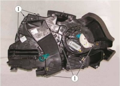
Figure 13-8 - Heater unit: 1 - heater block screws
Remove the evaporator 1, Figure 13-9, from the heater block.
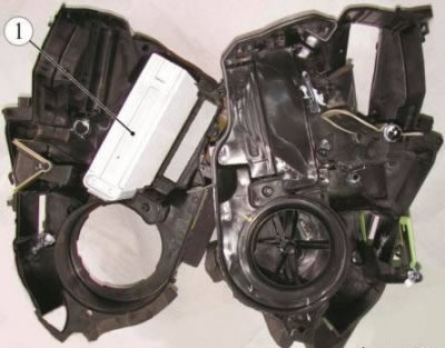
Figure 13-9 - Air conditioning evaporator: 1 - air conditioning evaporator
Assembly
Assemble the heater block in the reverse order, while:
- install new foam seals;
- install new sealing rings on the pipes of the heating system.