



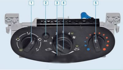
Heating, ventilation and air conditioning control unit: 1 – air direction regulator; 2 – air conditioning switch; 3 – air circulation mode switch; 4 – air fan mode switch; 5 – temperature control knob
Removal
Disconnect the negative battery terminal.
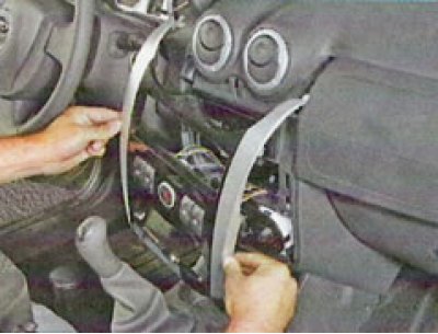
Remove the instrument panel center trim from the clips (see here).
Unscrew the two screws 1, Figure 14-6, securing the control unit to the instrument panel (torx T20 replaceable head, ratchet).
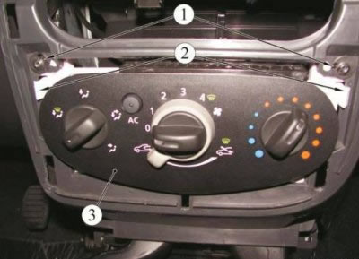
Figure 14-6 - Mounting the HVAC control unit: 1 - screw for fastening the heating, air conditioning and ventilation control unit; 2 - clamps; 3 - Heating, air conditioning and ventilation control unit
Squeeze the clamps 2 and remove the block.
Note: The block can be pulled out or pushed into the niche, depending on convenience
Turn the block over.
Disconnect connector 4, Figure 14-7, of the instrument panel wiring harness.
Disconnect the damper drive rods from the control unit. (remember the alignment of the rods before disconnecting).
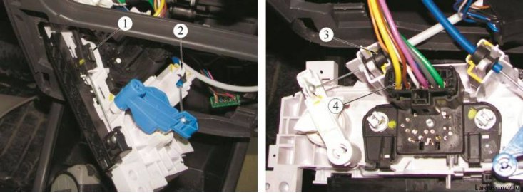
Figure 14-7 - Heater unit flap control rods: 1 - air recirculation flap rod; 2 - heater radiator flap rod; 3 - air distribution flap block rod; 4 - Instrument cluster wiring harness connector
If it is necessary to replace the lamps in the unit (total 2 pieces installed.) turn the cartridge (marked in the photo with yellow marks) corresponding lamp counterclockwise and remove it from the socket. (lamps used).
Installation
Install the heating, air conditioning and ventilation control unit in the reverse order.