



Removal
Place the vehicle in the work area. Raise the hood, disconnect the ground wire terminal from the battery.
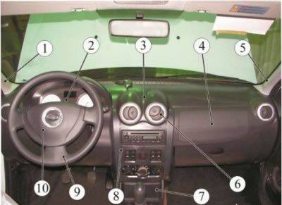
Figure 12-1 - Instrument cluster assembly: 1 - left windscreen pillar trim: 2 - instrument cluster; 3 - instrument panel; 4 - passenger airbag module (PAM); 5 - right windshield pillar trim; 6 - ventilation nozzle; 7 - floor tunnel lining; 8 - central instrument panel trim; 9 - steering wheel; 10 - Driver's MNPB
Lock the airbag control unit using a diagnostic tool.
Remove the driver airbag module (DABM).
Remove the steering wheel, steering wheel covers, paddle shifters, steering column adjustment knob and transponder receiver ring.
Having overcome the resistance of the clamps, fold back the decorative plug 1, Figure 122, unscrew the screw 2 and remove the rear part of the floor tunnel lining 3 (flat screwdriver, replaceable head Torx T20, ratchet).
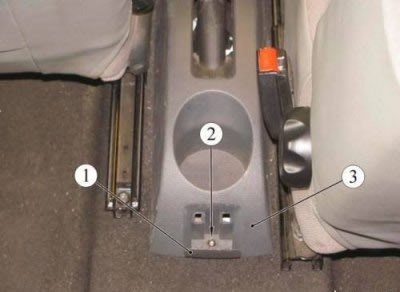
Figure 12-2 - Fastening the rear section of the floor tunnel lining: 1 - decorative plug; 2 - screw for fastening the rear part of the floor tunnel lining; 3 - rear part of the floor tunnel lining
Remove the two screws 1, Figure 12-3, securing the front part of the floor tunnel trim (torx T20 replaceable head, ratchet).
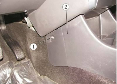
Figure 12-3 - Fastenings for the front part of the floor tunnel cladding: 1 - screw for fastening the front part of the floor tunnel lining; 2 - front part of the floor tunnel lining
Unscrew nut 4, Figure 12-4, and two screws 1. Remove cover 5 of the gear shift lever. Disconnect the wiring harness connector from the cigarette lighter 2 and remove the front part of the floor tunnel trim 3 (replacement head 10, Replacement head Torx T20, Extension, Ratchet).
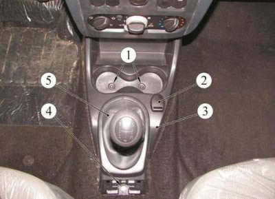
Figure 12-4 - Fastening the front section of the floor tunnel lining: 1 - screw for fastening the front part of the floor tunnel lining; 2 - cigarette lighter; 3 - Front part of the floor tunnel lining; 4 - nut for fastening the front part of the floor tunnel lining; 5 - gear shift lever cover
Remove the central trim 1, Figure 12-5, from the instrument panel, overcoming the force of the clamps. Disconnect the wiring harness connectors from the switches and remove the cover.
Remove the plug from the center console of the instrument panel or the radio with a CD player 2, disconnect the wiring harness connectors and the antenna (radio and CD player remover).
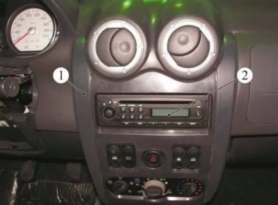
Figure 12-5 - Instrument cluster center console: 1 - central instrument panel trim; 2 - radio and CD player
Remove decorative trims 1 and 3, Figure 12-6, overcoming the force of the clamps.
Loosen the two screws 2 securing the instrument cluster visor and remove it, overcoming the force of the clamps (torx T20 replaceable head, ratchet).
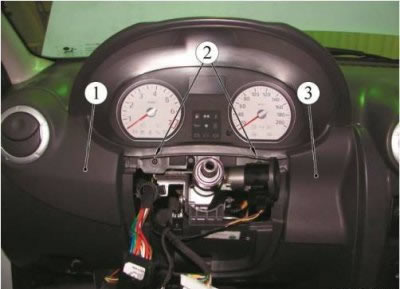
Figure 12-6 - Instrument panel decorative trims: 1 - left overlay; 2 - screw for fastening the instrument cluster visor; 3 - right overlay
Loosen the four screws 1, Fig. 12-7, securing the instrument cluster 2. Disconnect the two wiring harness connectors and remove the instrument cluster (torx T20 replaceable head, ratchet).
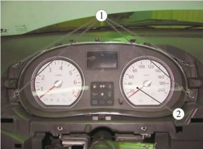
Figure 12-7 - Instrument cluster mounting: 1 - instrument cluster mounting screw; 2 - instrument cluster
Remove the left 1 and right 5 windshield pillar trims (see figure 12-1), overcoming the force of the clamps.
Remove handle 4, Fig. 12-8. Unscrew the two screws 3 securing the headlight corrector regulator 2, remove it from the hole in the instrument panel (torx T20 replaceable head, ratchet).
Having overcome the force of the clamps, fold back the decorative plugs 5 and unscrew one screw 1 of the lower fastening of the instrument panel on the left and right (torx T20 replaceable head, ratchet).
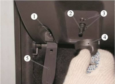
Figure 12-8 - Fastening the headlight corrector and instrument panel: 1 - screw for lower mounting of instrument panel; 2 - headlight corrector regulator; 3 - screw for fixing the headlight corrector; 4 - headlight corrector handle; 5 - decorative plug
Loosen screw 1, Fig. 12-9, securing the instrument panel through the window that opens after removing the radio and CD player (torx T20 replaceable head, extension, ratchet).
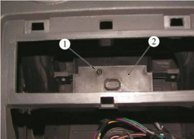
Figure 12-9 - Instrument cluster center mount: 1 - screw for central fastening of the instrument panel; 2 - instrument panel
Loosen the two screws 1, Figure 12-10, securing the heating, air conditioning and ventilation control unit 3 to the instrument panel, squeeze the clips 2 and push the unit into the instrument panel (torx T20 replaceable head, ratchet).
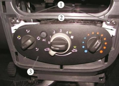
Figure 12-10 - Fastening the HVAC control unit: 1 - screw for fastening the heating, air conditioning and ventilation control unit; 2 - clamps; 3 - Heating, air conditioning and ventilation control unit
Unscrew the two screws 2, Figure 12-11, securing the instrument panel 1 to the heater housing (torx T20 replaceable head, extension, ratchet).
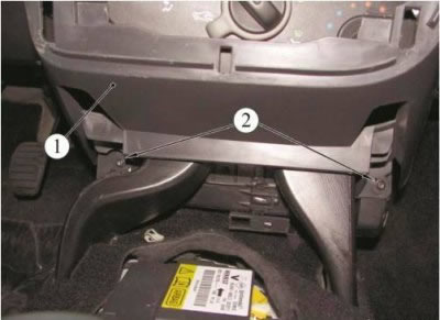
Figure 12-11 - Fastening the instrument panel to the heater body: 1 - instrument panel; 2 - screw for fastening the instrument panel to the heater body
Unscrew one screw 1 on the right and left sides, Figure 12-12, of the upper instrument panel mount 2 (torx T20 replaceable head, ratchet).
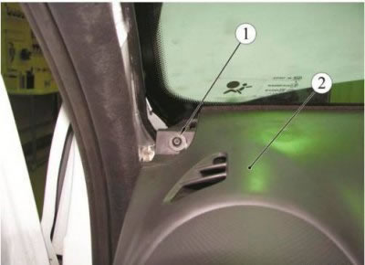
Figure 12-12 - Upper instrument panel mount: 1 - screw for upper fastening of instrument panel; 2 - instrument panel
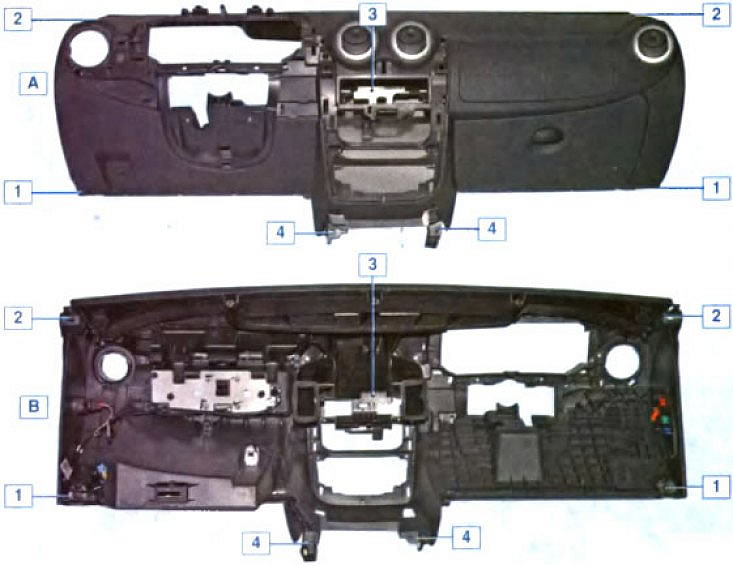
Instrument panel mounting points: A - outer side of the instrument panel; B - inner side of the instrument panel; 1 - lower side mount; 2 - top mount; 3 - central mount; 4 - lower mount
Remove the instrument panel. When removing, remove the diagnostic connector from the socket in the glove compartment and disconnect connector 1, Figure 12-13 (removal should be done with an assistant).
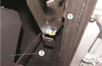
Figure 12-13 - Wiring harness connector: 1 - Wiring harness connector; 2 - instrument panel
Loosen the four nuts 2, Figure 12-14, securing the passenger airbag module 1, disconnect the wiring harness connector 3 and remove the passenger airbag module (replacement head 10, ratchet).
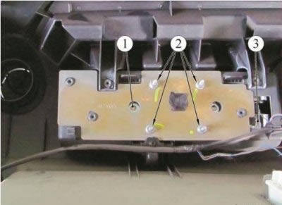
Figure 12-14 - Passenger airbag mounting: 1 - Passenger MNPB; 2 - passenger MNPB mounting nut; 3 - wiring harness block
Remove the outer ring 1, Figure 12-15, of the ventilation nozzle.
Remove the inner ring 2 of the ventilation nozzle and, having pressed the three clamps 3, remove the housing 4 of the ventilation nozzle from the instrument panel.
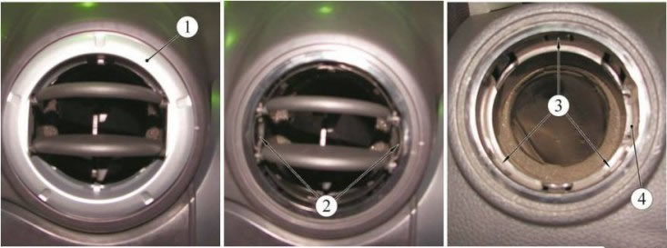
Figure 12-15 - Ventilation nozzle: 1 - outer ring of the ventilation nozzle; 2 - inner ring of the ventilation nozzle; 3 - retainer; 4 - ventilation nozzle housing
Installation
Install the removed parts in the reverse order of removal.
Unlock the airbag control unit using a diagnostic tool.