
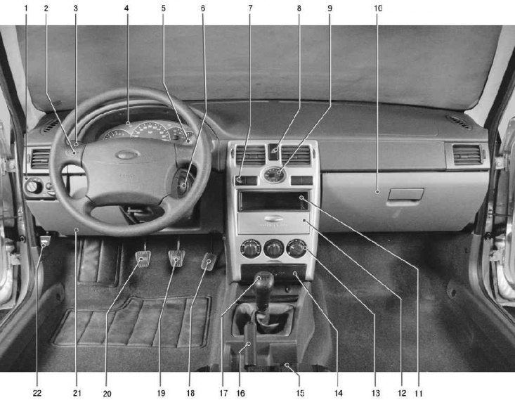
Pic. 1.6. Instrument panel and controls
The instrument panel contains the following instruments and controls (pic. 1.6).
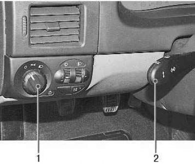
1 - control unit for outdoor lighting and instrument lighting.
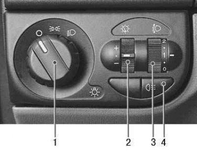
The control unit includes the following.
Switch 1 outdoor lighting can take three fixed positions. By turning the handle clockwise to the first fixed position, the outdoor lighting is turned on; when further turned to the second fixed position, the dipped or main beam of the headlights is switched on, depending on the position of the light signaling switch.
Regulator 2 instrument lighting. When the outdoor lighting is on, turn the knob to change the brightness of the instrument lighting.
Regulator 3 of the headlight beam corrector. When the headlights are on, turn the knob to change the direction of the headlight beam. The positions of the corrector regulator correspond to the following loading options:
- 0 - one driver or driver and passenger in the front seat;
- 1 - all places are occupied;
- 2 - all seats are occupied and the load in the trunk is not more than 50 kg;
- 3 - one driver and cargo in the trunk
Switch 4 rear fog lights. Pressing the switch button turns on the rear fog lights if the outside lights are on. Pressing the button again turns off the rear fog lights.
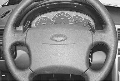
2 – sound signal switch. To turn on the horn, press the left or right steering wheel button with the corresponding symbol.
3 – the lever of the switch of indexes of turn and light of headlights. The switch turns on the direction indicators and the electrical circuits of the headlights with the ignition on, depending on the position of the handle 1 of the outdoor lighting switch.
The switch lever 2 can take the following positions.
In the vertical plane:
- I (middle lever position) - direction indicators are off. All external lighting is turned off, side lights are on, dipped or main beam headlights are on, depending on the position of the ignition key and handle 1 of the outdoor lighting switch;
- II (lever moved down a bit) - left turn indicators included (non-fixed position);
- III (lever moved down a bit) - left turn indicators included (fixed position);
- IV (lever moved up a bit) - right turn indicators included (non-fixed position);
- V - enabled (lever moved up) right turn indicators (fixed position).
In the horizontal plane:
- VI (to myself) - high beam headlights are on regardless of the position of the outdoor lighting switch (non-fixed position);
- VII (Push) - high beam headlights are on, if the handle 1 of the outdoor light switch is turned towards the low beam symbol (fixed position).
4 - a combination of devices.
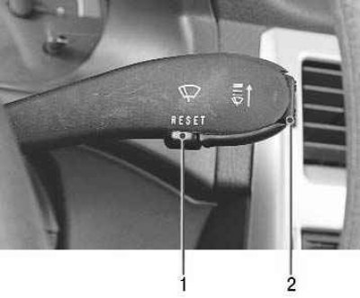
5 - lever switch cleaners and washer glasses. The switch includes electrical circuits with the ignition on.
The switch lever can take the following positions.
In the vertical plane:
- I (lower lever position) - windshield wipers and washers are off;
- II (lever moved up a bit) - intermittent windshield wiper operation is enabled (non-fixed position);
- III (lever moved higher) - intermittent windshield wiper operation is enabled (fixed position);
- IV (lever moved higher) - the first speed of the windshield wiper is on (fixed position);
- V (lever moved higher) - the second speed of a windshield wiper is included (fixed position).
In the horizontal plane:
- VI (to myself) - windshield washer on (non-fixed position);
- VII* (Push) - tailgate glass cleaner included (fixed position);
- VIII* (Push) - additionally included washer glass tailgate (non-fixed position).
* For hatchback or station wagon vehicles.
Buttons 1 and 2 are installed on the right and lower ends of the lever (see photo), used to control the trip computer (see «Trip computer»).
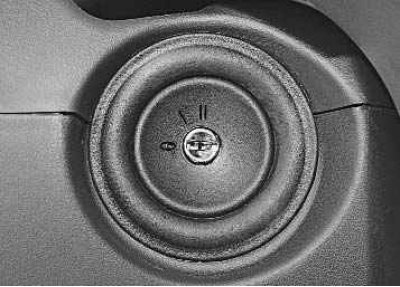
6 - switch (lock) ignition, integrated with the anti-theft device, is located on the right side of the steering column. The key in the lock can take one of three positions:
- 0 - disabled. The position is fixed, the key is removed. When the key is removed, the locking mechanism of the anti-theft device is activated. To securely lock the steering shaft, turn the steering wheel to the right or left until it clicks. To turn off the mechanical anti-theft device, insert the key into the ignition switch and, while slightly turning the steering wheel to the right and left, turn the key to the position «I»;
- I - ignition. The position is fixed, the ignition is on, the key cannot be removed, the steering is unlocked;
- II - starter. The position is not fixed, the key cannot be removed, the steering is unlocked. It is achieved by turning the key clockwise against the force of the spring. To operate the starter, you need to hold the key with your hand. The ignition switch is equipped with a starter restart lock when the engine is running. To restart the starter after an unsuccessful attempt to start, move the key from the position «I» into position «0», and then back to position «II».
Attention! Don't hold the key in position «II» more than 10 s.
Attention! It is strictly forbidden to turn off the ignition and remove the key from the ignition switch while driving, as this will lead to a sharp increase in the effort on the brake pedal and steering lock.
Note. If the ignition is turned off and the key is left in the ignition, when the driver's door is opened, the buzzer emits a continuous trill to warn that the key has been left in the ignition.
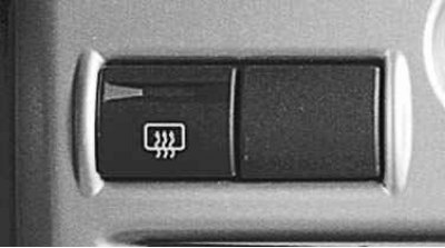
7 – the switch of heating of back glass. When you press the switch button, the rear window heating is switched on, and the control lamp in the button lights up. Pressing again turns off the heating.
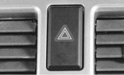
8 - alarm switch. When the switch key is pressed, all direction indicators and the control lamp installed in the key light up with a flashing light. Pressing the key again turns off the alarm.
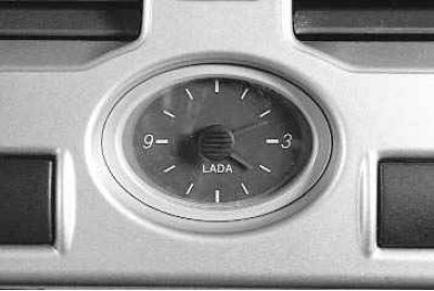
9 - hours. When you press the button located in the center of the dial, the clock is translated.
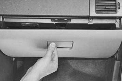
10 - glove box cover. To open it, pull the lock button and lower the glove box lid. If the ignition is switched on, the interior light for the glove box comes on.
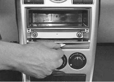
11 - socket for radio equipment. Installation of radio equipment is provided, corresponding in size and method of fastening to international standards.
12 - compartment for small items. Plastic cap with inscription «OPEN» equipped with two latches in the upper part, preventing spontaneous opening of the lid. The compartment has a special rubber mat.
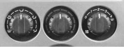
13 - control unit for the heating and ventilation system salon. The methods for controlling the heating and ventilation of the passenger compartment are described below (see «Heating and ventilation»).
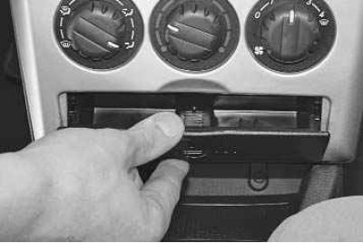
14 - front ashtray. To use the ashtray, pull the lid towards you by grasping its top tab.
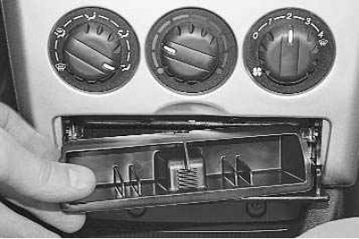
To clean the ashtray, pull it out of the socket by pulling it towards you.
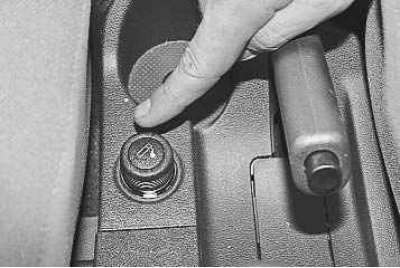
15 - cigarette lighter. To use the cigarette lighter, press the button on its moving part.
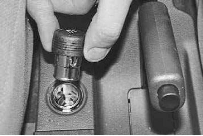
After heating the coil for about 10-20 seconds, the movable part will automatically return to its original position with a click, and the cigarette lighter can be removed for use.
Attention! The cigarette lighter can be turned on again no earlier than after 20 s.
Attention! Do not forcibly hold the cigarette lighter in the pressed position.
Attention! Do not use the cigarette lighter socket to connect powerful electrical appliances (electric coffee maker, etc.) – this may cause damage to the electrical equipment of the vehicle.
Attention! If the cigarette lighter button does not return to its original position 30 seconds after switching on, remove the cigarette lighter from the cartridge to prevent the coil from burning out.
16 - parking brake lever. To brake the vehicle with the parking brake, lift the lever all the way up. At the same time, the control lamp in the instrument cluster will light up red and the brakes of the rear wheels will be blocked. In order to brake the car, pull the lever up a little, press the button on the end of the lever handle and lower the lever all the way down - the control lamp should go out.
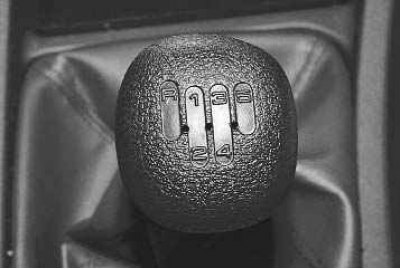
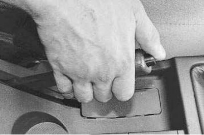
17 - shift lever gears. The gearshift pattern is applied to the lever handle.
18 - accelerator pedal.
19 - brake pedal.
20 - clutch pedal.
21 - cover of the mounting block of fuses and relays. Replacing fuses and relays is described in sec. «electrical equipment» (see «Replacing fuses and relays in the mounting block»).
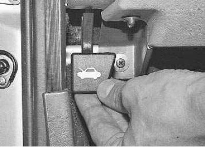
22 - hood lock drive lever. By turning the lever towards you, the hood lock is unlocked.