



During operation, the ECU monitors the serviceability of all elements and circuits of the engine control system. Having detected a malfunction, the ECU switches the engine management system to the backup operating mode and turns on the engine malfunction indicator lamp located on the instrument panel. The engine will still be able to continue working (except in case of crankshaft position sensor failure), which allows you to get to the repair site under your own power. The ECU records the codes of detected faults into the random access memory (RAM).
To read fault codes, an external diagnostic device, such as DST-2M, must be connected to the engine management system. The system has a diagnostic connector for this purpose. Access to the connector block is covered by a decorative cover (see above).
To open the cover, pry it off with a screwdriver from the center console side of the instrument panel (see "Engine Management System Fuses and Relays - Replacement").
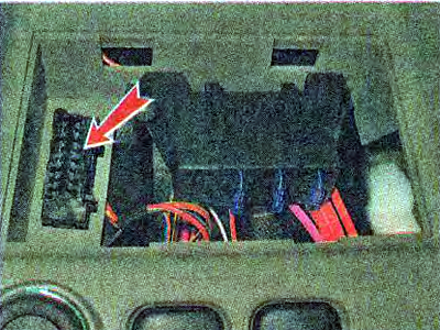
You can read the fault codes at a service center that has the necessary equipment.
When servicing and repairing the engine management system, the following precautions must be observed:
- Do not touch the ECU terminals with your hands - the engine management system is microprocessor-based, the electronic components of the ECU can be damaged by electrostatic discharge.
- Getting Started with Car Repairs (especially if the operations involve dismantling elements of the engine management system), remove the terminal from the negative terminal of the battery.
When the battery is disconnected from the vehicle's network, the fault codes will be cleared from the ECU memory.
- In many cases, testing engine control system components requires the presence of supply voltage in the system's electrical circuit. In this case, disconnecting the wire blocks from the sensors and actuators of the engine control system is allowed only after turning off the ignition.
- You can disconnect the wiring harness connector from the ECU only after removing the terminal from the negative terminal of the battery.
- If it is necessary to connect the battery to the vehicle's electrical system during repairs, first make sure that the disconnected wires (terminals of the pads, ends of the wires) do not short to ground and that the ignition is off. Connect the terminal to the positive terminal of the battery first, then to the negative terminal. Turn on the ignition only during the measurement period.
- The engine management system uses electronic components with a supply voltage of 5 V. They are supplied with voltage from the vehicle's electrical network (voltage in which is more than 12 V) will result in failure of the engine management system.
- To check the engine management system, use a multimeter; the internal resistance of the device in voltmeter mode should be at least 10 MOhm. If necessary, to check the power supply circuits under 12 V, you can use a test lamp, but the lamp power should be less than 4 W (the instrument panel test lamp A 12-1.2-1, power 1.2 W, or the cigarette lighter backlight lamp AMN 12-3-1 - 3 W will do).
- Before starting the engine, make sure the terminals are securely connected to the battery posts.
- To avoid damage to the electronic components of the ECU, do not disconnect the wire terminals from the battery terminals while the engine is running.
Note: Checking the condition of the engine management system components is shown below in the relevant sections of the chapter "Engine Management System".