
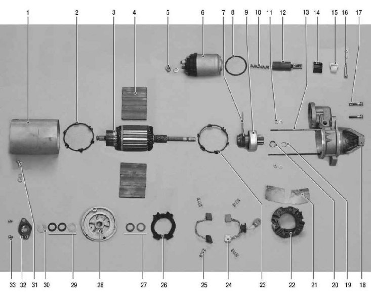
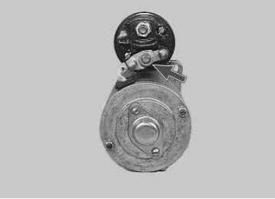
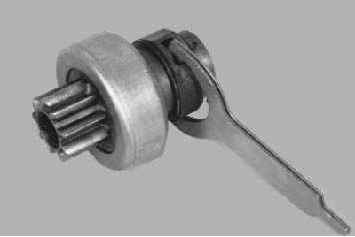
Pic. 10.4. Starter details 2111.3708010-01: 1 - body; 2 - thrust ring from the side of the collector; 3 - anchor; 4 – permanent magnet; 5 – a nut of fastening of the tire of brushes of positive polarity; 6 - traction relay; 7 – drive lever; 8 - sealing ring; 9 - freewheel; 10 - return spring; 11 - tie rod nut; 12 – relay armature; 13 - tie rod; 14 - sealant; 15 - lever support; 16 - the axis of the lever; 17 - screws for fastening the traction relay; 18 - front cover; 19 - retaining ring; 20 - restrictive ring; 21 - insulator; 22 - internal brush holder; 23 - thrust ring on the drive side; 24- «positive» brush; 25 - clamping spring; 26 - external brush holder; 27 - internal spacers; 28 - back cover with a sleeve; 29 - external spacers; 30 - lock washer; 31 – a bolt of fastening of the tire of brushes of negative polarity; 32 – armature shaft cover; 33 – anchor shaft cover bolt
On fig. 10.4 shows the details of the starter. Before disassembling the starter, make sure it is defective by following these simple checks.
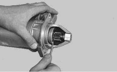
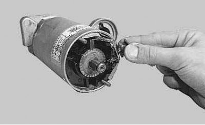
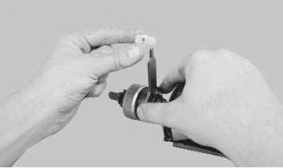
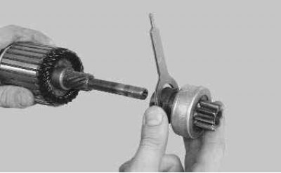
1. Use a screwdriver to check the ease of movement of the drive coupling along the shaft.
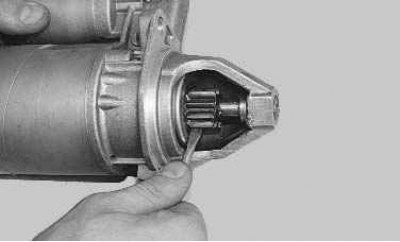
2. Rotate the drive gear. It should rotate easily relative to the coupling hub in the direction of rotation of the armature and should not rotate in the opposite direction.
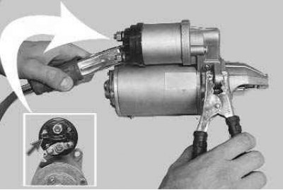
3. Wire for «smoking» terminal «minus» the battery removed from the car with the starter housing. Connect the second wire at one end to the terminal «plus» battery, and the second - to the output of the control wire of the traction relay. If the traction relay is working properly, a click will be heard and the drive clutch will extend. Otherwise, the traction relay must be replaced.
4. Disconnect the wire from the control output of the traction relay and connect it to the bottom contact bolt of the traction relay. The starter armature should begin to rotate at a frequency of more than 5000 min-1. Otherwise, repair the starter.
You will need: keys «for 8», «on 10», «at 13», screwdriver with a flat blade, pliers with narrow jaws, hammer, tester, caliper.
1. Remove the starter from the car (see «Removal and installation of a starter»).
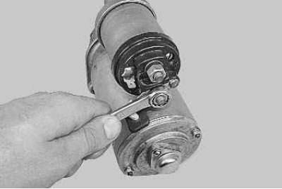
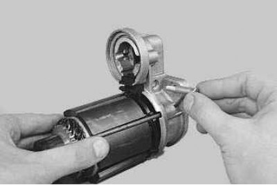
2. Turn away a nut of fastening of the tire to a contact bolt.
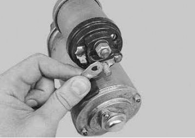
3. Disconnect the tire from a contact bolt of the traction relay.
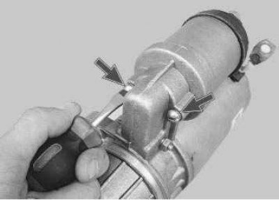
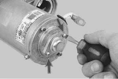
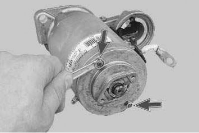
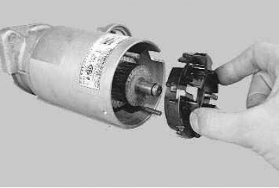
4. Turn out two screws of fastening of the traction relay...
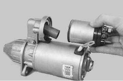
5.... and remove the relay.
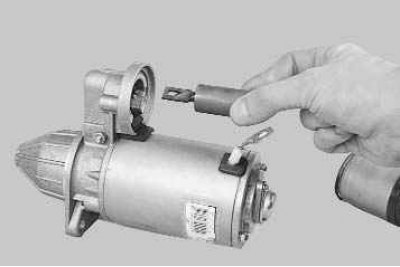
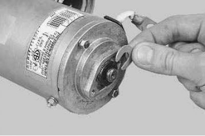
6. Remove the anchor of the traction relay by lifting it up so that the anchor loop is removed from the lever.
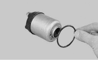
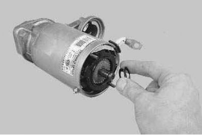
7. Remove the sealing ring from the traction relay housing...
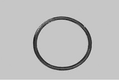
Note. If the ring is heavily compressed, cracked or has lost its elasticity, replace it with a new one.
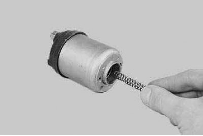
8.... and remove the return spring.
9. Remove two screws...
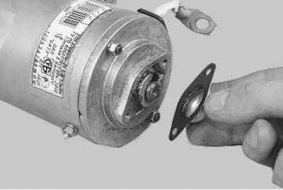
10.... and remove the armature shaft cover...
11.... lock washer...
12.... and distance washers.
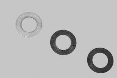
Note. Remember the order in which the spacers are installed, as they are of different thicknesses. When assembling the starter, install the washers in the same sequence.
13. Turn out two nuts of coupling hairpins...
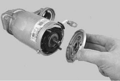
14.... and remove the cover from the collector side from the starter armature shaft.
15. Remove two spacers...
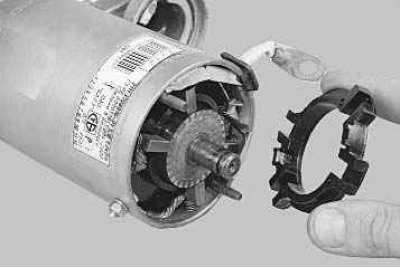
16.... and an external brush holder.
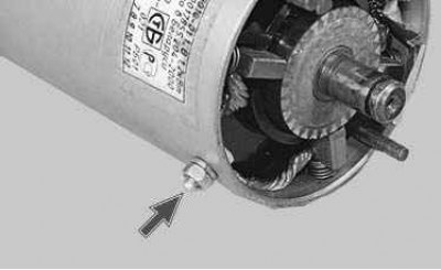
17. Turn out a nut of fastening of brushes of negative polarity...
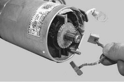
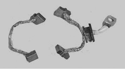
18.... and carefully, so as not to damage the brushes, remove them together with the pressure springs. Replace heavily compressed or bent springs.
19. Remove the positive polarity brushes in the same way.
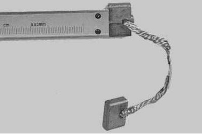
Note. Measure the height of the brushes from the edge of the work surface to the copper pigtail of wires.
If their height is less than 4 mm, replace the brushes with a set (4 things).
20. Remove the paper insulator of the positive polarity brushes...
21.... and an internal brush holder.
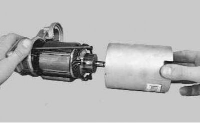
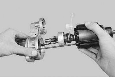
22. Remove the rotor with magnets and front cover from the starter housing.
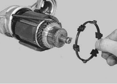
23. Remove the retaining ring of the magnets from the manifold side.
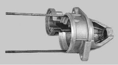
24. Turn out an axis of the lever, having previously unscrewed a lock nut from the other side...
25.... and remove the axle.
26. Remove the cover from the drive side.
27. Inspect the starter covers; if cracks are found, replace them. If the bushings located in the covers, in which the armature shaft rotates, are worn out, have scuff marks, shells and other defects, replace the bushings or covers with defective bushings...
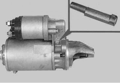
28.... having previously unscrewed the tie rods from the cover on the drive side.
29. Remove the lever support.
30. Replace a cracked or significantly worn support with a new one.
31. Remove the six magnets from the anchor, after marking or remembering their relative position.
Note. Incorrect installation of the magnets may result in a reduction in starter power or reverse rotation.
32. Remove the thrust ring of the magnets from the drive side.
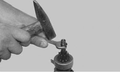
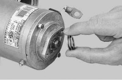
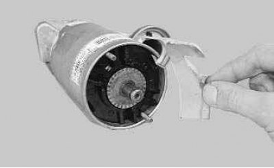
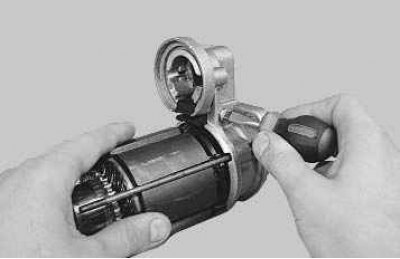
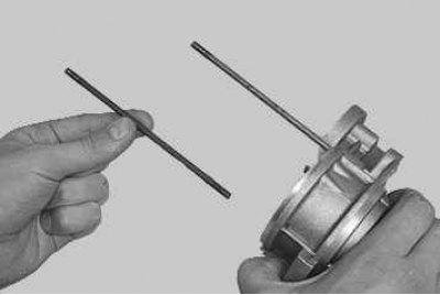
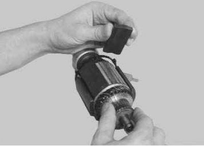
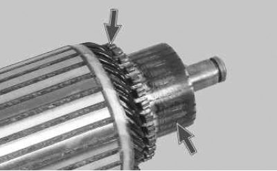
33. Having installed the drive shaft on a wooden block, with clear hammer blows, slide the restrictive ring along the armature shaft, as shown in the photo.
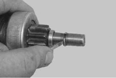
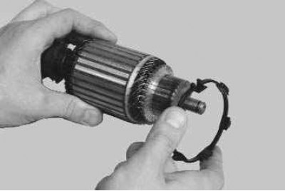
34. Prying off with a screwdriver...
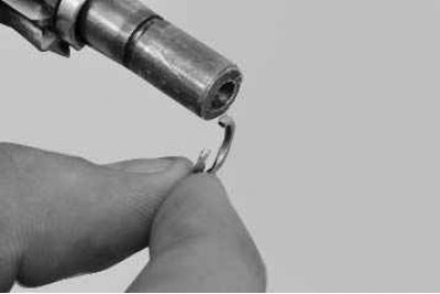
35.... remove the retaining ring...
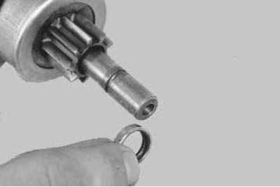
36....then the restrictive ring...
37.... and remove the overrunning clutch assembly with the lever from the armature shaft.
38. Examine the anchor. If the collector is dirty or there are marks, scratches and other defects on it, sand the collector with fine-grained sandpaper. With a significant roughness of the collector or protrusion of mica between its plates, machine the collector on a lathe and then grind it with fine-grained glass sandpaper. The runout of the collector relative to the pins of the shaft should not exceed 0.05 mm. Remove the yellow coating found on the armature shaft from the bearing with a fine-grained sandpaper, as it can cause the gear to seize on the shaft. Check the reliability of the soldering of the armature winding leads to the collector plates. Inspect the winding at the ends of the anchor. The winding diameter must be less than the armature iron package. Otherwise, replace the anchor.
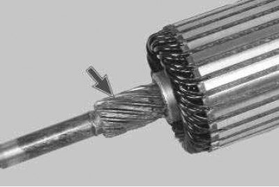
39. Inspect the condition of the splined connection of the armature shaft for damage in the form of nicks and roughness. If possible, remove minor damage with fine-grained sandpaper.
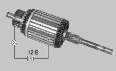
40. Check the condition of the armature winding using a test lamp powered by 12 V. Supply voltage to the collector plate and armature core - the lamp should not burn. If the lamp is on, then there is a short circuit in the armature winding or collector plate on «mass». In this case, replace the anchor.
41. Check whether the armature of the starter traction relay moves easily, whether the contact bolts are closed with a contact plate (using a tester).
42. Check drive. The drive gear teeth must not show significant wear. The gear should turn easily relative to the clutch hub in the direction of rotation of the armature and should not turn in the opposite direction. If the gear teeth are worn or damaged, or the gear turns in both directions, replace the drive. There should be no cracks on the starter drive lever.
43. Assemble the starter in the reverse order of disassembly, taking into account the following features:
- lubricate the splined surface of the armature shaft with General Electric CG321 silicone grease or equivalent;
Attention! During operation, the drive clutch does not need to be lubricated. However, it must be cleaned of dirt. Do not use cleaners to clean the drive that can wash out the lubricant embedded in its coupling.
- lubricate the bearings with engine oil (bushings) in starter covers;
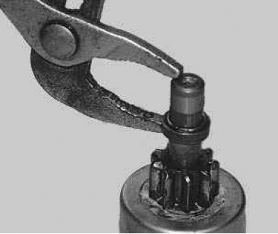
- use pliers to install the restrictive ring;
- before installing the traction relay, apply a thin layer of silicone sealant to its surface in contact with the starter cover on the drive side.
44. After assembling the starter, turn on the traction relay (see point 3) and measure the gap between the end of the gear and the thrust ring, it should be 3–5 mm.
45. If the gap is not included in the specified range of values, adjust it by turning the axis of the lever, the body of which is made in the form of an eccentric. To do this, loosen the locknut, rotate the axle and tighten the locknut. After the final assembly, it is recommended to check the starter at the service station at the mod stand. 532M.